S S T C 2
A Weekend Solid State Tesla Coil
& my guide to How to
Build a SSTC! |
How to build a Solid State Tesla Coil
If you are here to learn how to build a SSTC, you have come to the
right place! Welcome!
The design and construction a Solid State Tesla Coil (a Tesla Coil
powered by Transistors instead of a spark gap) is not a trivial task.
However, the basic mechanism and workings of a SSTC are not too
complicated. The main challenge in building a SSTC lies with
the fact that the builder should have a good understanding & experience with electronics,
and have some test equipment (oscilloscope is required) for
debugging, which many beginners may not have. There are also several subtle but important things to take note of
which are usually difficult to find information about.
Unlike spark-gap or vacuum tube Tesla Coils, building an SSTC is not as straightforward as copying a
schematic. When I began building SSTCs a few years years ago, I found it
difficult to find information on how to build one, and what to look out
for.
Most tesla-coilers, through their own coiling successes and
mistakes, have developed an intuitive understanding of the nuances of SSTC
construction, and perhaps found them not worthy of specific mention.
This has led to the motivation to write this page - a basic practical guide to
Solid State Tesla Coils. I hope to write a useful and concise
document aimed at the budding coiler who has perhaps built a Spark Gap
Tesla Coil before, and wishes to move on to transistor Tesla Coils.
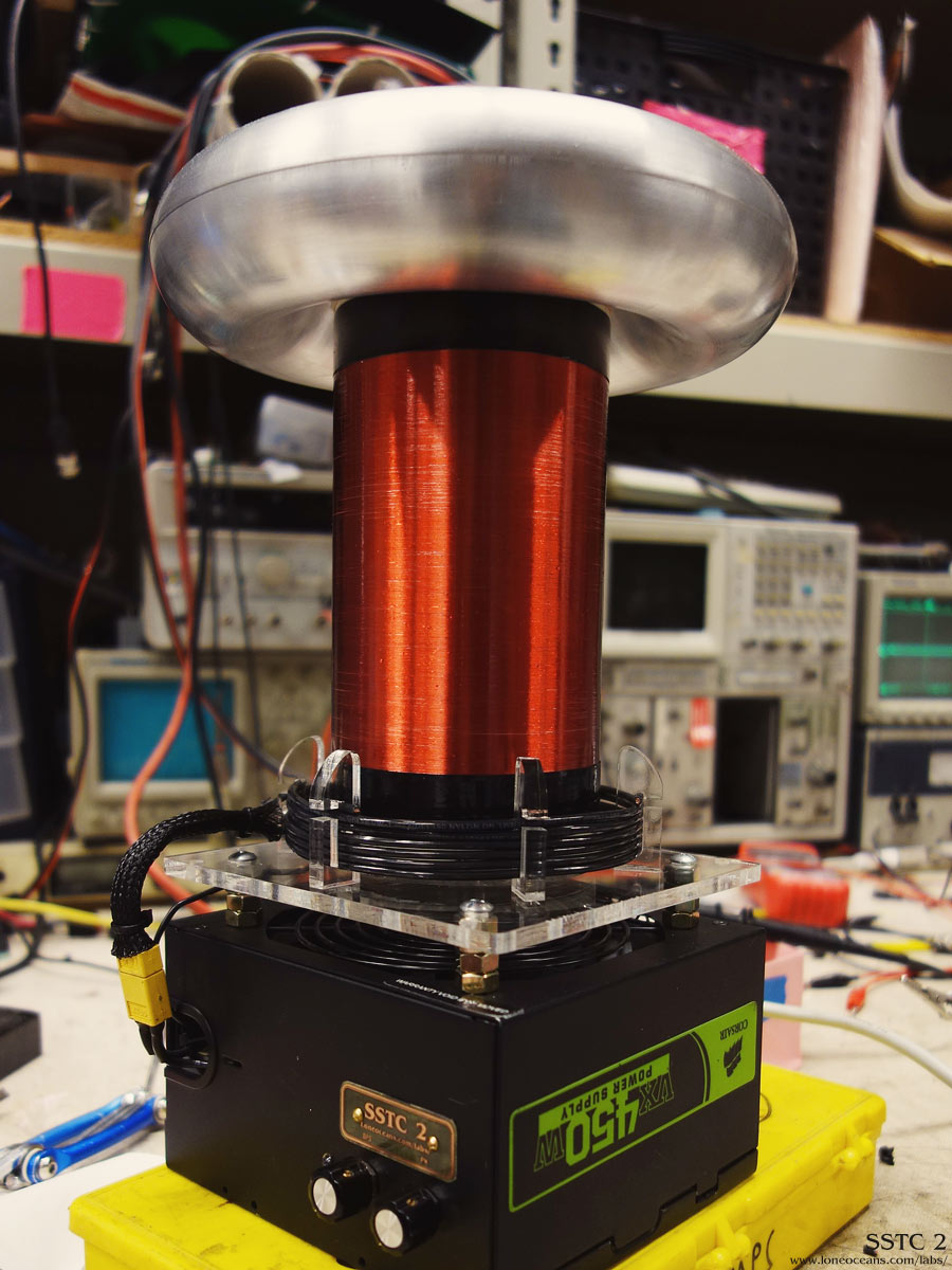
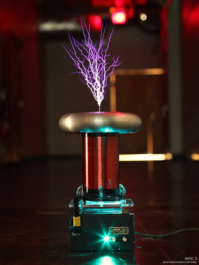
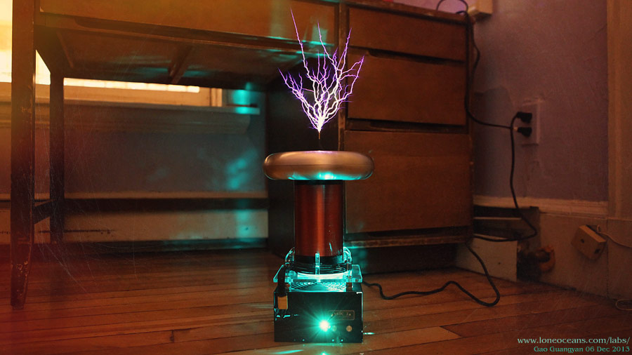
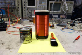
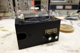
I will document this guide through the construction of a very simple Solid
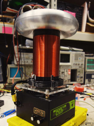
State Tesla Coil - SSTC 2 - which I have designed to be simple, compact, and produces
good results. I will try to explain some of my design choices. Also, I wanted to see what I was able to cook up in a
one busy weekend in school! The result is the photo shown on the right
(and actually took 2 weekends to complete.. but that's not too bad I
hope!)
You might also be interested in my previous Spark Gap Tesla Coils,
Tesla Coil 1 and
Tesla Coil 2.
Also, check out my first SSTC 1, along with my
newer DRSSTC 1, DRSSTC
2 and DRSSTC 3 coils - a more powerful variant of the SSTC.
Thanks for
visiting my page and if you have any questions, wish to share your
projects, or feel that my projects have inspired you in one way or
another, feel free to email me at loneoceans[at]gmail(dot)com. I'd love
to hear about your projects too. Additionally, if you find any mistakes
in my write up, feel free to drop me a note! If this page was helpful,
feel free to share it with others too!
I would appreciate any credit if you choose to use any
of the design / code for your own projects. Good luck! Finally, I would
like to thank the very many people especially Steve Ward, Bayley and
Phillip whom I had very many conversations with and helped me in writing
this guide.
Page Contents
1. Introduction
2. Components of a SSTC
3. Construction of a Weekend Coil
4. Results and Media
5. Credits and Links
SSTC 2 Final Specifications (05 Nov 2013)
- 120VAC input (+-170 across primary)
- 249kHz Resonant Frequency
- Half Bridge of Fairchild HGTG30N60A4D IGBTs
- 3.5" x 6.25" secondary with 34 AWG (~975 turns)
- 4.56 x 0.65" 6 turn primary with 14 AWG
- Secondary current feedback (50:1 ferrite transformer)
- 8" x 1.9" stamped aluminium toroid
- Interrupter - 0 to 1500us, 1 to 254Hz via ATtiny85
- Spark Length to air ~9" (22.5cm) (05 Nov 2013)
For much more videos and images of the coil in action, please scroll down to
Results!
10 Oct 2013
Introduction
Before I begin, it is good to have a basic understanding
of how a Tesla Coil works. For that matter,
Wikipedia provides
a good narrative and overview. Also, caveat - if any of you more
experienced coilers out there finds some mistake in my write up, feel
free to notify me for me to fix it! :) Finally, if you are a serious
hobbyist who doesn't have an oscilloscope, I would say it is mandatory
to buy yourself a scope for you to really grow as an engineer! You can
pick an old analog one up cheap for less than $100 these days, and you
will really need it for debugging your SSTC.
Tesla Coils
A Tesla Coil is an air-cored resonant transformer
capable of generating extremely high voltages. Its construction is
relatively straightforward, but the theory is a bit more involved. The
key concept of a Tesla Coil is its resonant property, where a
Resistor-Inductor-Capacitor (RLC) resonant circuit is energized at its
resonant frequency, developing very high voltages.
A Tesla Coil consists of two concentric coils which are
not electrically connected to each other. The Primary Coil usually
consists of a few turns of heavy wire, and has a shape ranging from a
solenoid to a flat spiral. This coil is usually connected to some
capacitor, forming the Primary LC circuit (if you are unfamiliar with
RLC circuits, feel free to browse Wikipedia for a quick introduction).
The secondary circuit consists of a long coil of wire, usually having
several hundreds to thousands of turns wound on a pipe, and placed
concentrically in the middle of the coil.
Game plan: For a
normal SSTC, we will focus on creating some sort of circuit
to energize
the secondary coil at its resonant frequency.
* Note that SSTC operation
differs slightly from Spark Gap Tesla Coils or the newer Double Resonant
Solid State Tesla Coils, where the primary circuit is also oscillating
at a resonant frequency similar to the secondary coil. In a conventional
SSTC, the primary circuit is not resonant. *
How does a SSTC work?
Simply put, a normal Solid State Tesla Coil (SSTC) is simply a power
amplifier driving a primary coil at the resonant frequency of the
secondary coil. As mentioned, the secondary circuit is a coil of wire,
one end of which is grounded, and the other end is connected to some kind
of topload (metallic volume) at the top of the tube. This topload is usually in the shape
of a toroid (looks like a doughnut). The toroid provides some sort of
capacitance to the secondary, its shape serves well in
electric field control, and also looks cool! However, other shapes such
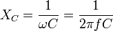
as spheres are also common. This topload capacitance (usually small, on
the order of pF - can be calculated) and secondary coil in series form
an L (inductor) C (Capacitor) circuit with a resonant frequency
described by:
The ratio of L and C also determines the Q-factor of the
system (which affects the selectivity, or how narrow its resonant peak
is). Think about the resonant frequency as if the circuit was like a
swing, which naturally wants to swing at a certain rate. Our goal is
then to find a way to drive this primary coil at the secondary's
resonant frequency.
The way we achieve this is by switching power into the
primary coil at the resonant frequency of the secondary. We do this by
creating
a high-voltage square wave across the primary coil using an
inverter circuit. This circuit comes in two common forms - a half bridge or a full
bridge. Line voltage (120 or 240VAC depending where you live) is
rectified and stored in a large bus capacitor (several hundred to
thousands of uF), and the inverter works to create an AC square wave
across the primary. The result of this is a sinusoidal current in
the primary coil due to it being driving at resonance.
Next, we need to know what the resonant
frequency is. To determine the correct frequency to drive the coil, an
external oscillator can be used (requires tuning), or feedback can be
taken from the secondary or primary coil for self-oscillation.
*note* A DRSSTC differs from this with the addition of a
primary tank capacitor in series with the primary coil. The goal
here instead is to not only drive the secondary at resonance, but to also drive
the primary at the same resonant frequency. Now, as the inverter
switches the primary, the current is still sinusoidal, but grows.
Additionally, due to resonance, the primary voltage also increases from
line voltage up to the several kV. This gives the primary a better
impedance match to secondary circuit. The current also increases up to
several hundred (to thousands) Amperes. Due to this second resonance,
this variant of SSTCs are known as Double Resonant SSTCs. The
result is much larger sparks in the output!
When the secondary coil is driven at resonance, a large
voltage develops across the coil. Using an example of a swing, if we keep
supplying 'pushes' at the correct resonant frequency, the swing gets
higher and higher. Similarly, a large voltage develops on the top load,
eventually leading to electrical ionization and breakdown of the air,
forming sparks.
With a basic understanding of how an SSTC works, lets
see how we can get all the parts working together.
Parts of a SSTC
Let us break down the SSTC into is fundamental
building blocks. The are three main parts to the system.
-
The
first is the low-voltage logic control and gate driver.
This part creates the signals to drive our inverter (half or
full bridge). In this circuit, we find a way to generate the
correct frequency either via feedback or by an external
oscillator, and then create appropriate signals to drive our
transistors in the inverter.
-
The second is the high mains-voltage inverter
itself,
which drives the primary coil. This circuit handles the big
currents, and also consists of our rectification system (from
mains to a big capacitor), as well as a set of large power
transistors. MOSFETs have been used in SSTCs, but IGBTs have
become popular choices.
-
The last circuit is the
secondary coil which basically consists of only the coil and
the topload, and is electrically isolated from the previous two
circuits.
-
Driving the SSTC in continuous mode consumes large amounts of power and heats up the
transistors
significantly. Hence, SSTCs these days often come with an
interrupter, which is basically a small controller which
turns the gate driver on and off. This
allows the user to control the duty cycle of the SSTC. The
interrupter controls the pulse-width, which is the
duration the inverter is turned on (usually from 10 to 300us in
DRSSTCs, and up to several ms in SSTCs), and the
breaks-per-second.
We will examine these parts in detail in
the next section.
Making Music with the SSTC
With the interrupter, we can now create a
variety of modes to drive the SSTC! For example, I could set my
interrupter to turn the tesla coil on at 200 Hz with about 10%
duty cycle. This means we turn the tesla coil on for 500us, 200
times a second. Each pulse makes a spark and an associated 'bzzt'
sound. If we make this sound 200 times a second, we end up with
a note at 200Hz (albeit a rather harsh one). We can vary this
frequency and produce different notes (you can think of this
like FM)! This is the basis for most musical Tesla Coils today.
The second method is more involved and will not
be discussed further here. But the basic principle is to run the
SSTC in continuous-wave mode (no interrupter, so it is on all
the time), but modulate the input voltage to the inverter with
the envelope of the music (think of this as AM)! This allows a
greater fidelity in output power. Consequently the spark that is
created grows and contracts based on the input power, creating
air pressure waves which are heard as music.
Components of a Solid State Tesla Coil
Let us now discuss in more detail the basic
building blocks of a SSTC. I will explain these through the
design of an actual SSTC. Before I build the
coil, lets think about the design a bit more first:
Power Inverter
The goal of the inverter is to produce a square
AC wave across the primary coil.
Bus Supply
The bus supply as it is named, supplies the
power to the input of the inverter. This is usually rectified
mains AC, which can simply be stored in a large electrolytic
capacitor. During switching, the inverter pulls power from this
capacitor (several tens to hundreds of Amperes for the short
duration of the on-time), which is driven into the primary coil.
The capacitor is important to supply this large current draw. In
addition, we do not wish for the voltage to drop too much during
the on-pulse, hence we want a large capacitor. Typical values
begin at around 1000uF. A few hundred uF works fine for small
coils.
As I am currently in the United States, I have
to work with 120VAC line voltage. After rectification, this is
just about 170VDC, which would give me +-85V in half-bridge
configuration. However, running the primary at higher
voltages produces bigger sparks! To increase the voltage supplied to my
bus, I have used a simple voltage doubler circuit, which
essentially produces 120V * 2 * (Sqrt 2) volts DC (about
340VDC). This is supplied to two 250V 1000uF capacitors (in
series), providing a bus capacitance of 500uF at 500V (charged
to 340VDC). Do not forget to add bleeder resistors across the capacitors to
make the device safer! 100k resistors should do the trick.
Configuration
There are two possible layouts for the inverter
- a half bridge or a full bridge.
The main advantage of the half bridge is
simplicity and lower part count. However, the advantage of a
full bridge is twice as much voltage across the primary and
hence most possible power. In this coil, a half bridge has been
chosen for ease and compactness, but this can be easily extended
to a full-bridge. Since I have a voltage doubler making my bus
340VDC, my primary coil sees +-170V across.
One important thing to note in the physical
design of the bridge is to minimize stray inductance.
This is done by keeping any leads or wires physically as close
together as possible. Because large currents will be flowing in
our bridge, the switching can induce large voltage spikes if our
inductance is too large. To solve this problem, I have used a
PCB with a laminated bus structure for my half-bridge. Check out
my SSTC 1 for how I did it using wires
instead.
Keep your bus capacitor as close to the transistors as possible,
and make sure that the transistors are mounted on a heat-sink.
Additional things to take note of include adding
subber capacitors to the IGBTs (film capacitors mounted
physically close to the IGBT - these are meant to soak up
transient high voltage spikes and thus are usually rated around
1kV and 1 to 6uF - I have omitted them in my design because of
the low-inductance layout of my bridge. Also, adding Transient
Voltage Suppressors across the CE of the IGBT (or DS of the
MOSFET) - usually bidrectional TVS of the 1.5KE220 type are used
(series if required), and minimizing bus inductance as much
as possible to reduce voltage spikes. Running the transistors no
more than 2/3 of their specific voltage rating is good practice
also.
Transistor Selection
SSTCs have traditionally been powered by MOSFETs
(metal oxide semiconductor field-effect transistor) instead of
the more common bipolar transistor. In a normal bipolar
transistor, a small base current is used to drive a large
emitter-collector current. In this way, BJTs are
current-operated devices. However, in a SSTC operation where we
may be switching significant currents (several tens to a hundred
Amps) at high frequencies, we will need large currents (on the
order of several 0.1 to 1A) to switch our transistor, making
this very challenging.
A MOSFET is a voltage-operated device, where a
small gate voltage switches a large drain-source current. They
are very nice as switches due to their high off-resistance, low
on-resistance and only require a small gate current to turn-on
(basically charging up a small capacitor in the gate to turn it
on). Their fast switching speed is ideal for SSTCs. However,
MOSFETs are more sensitive to static, and more expensive.
In recent years, the demand for power
electronics (e.g. inverter applications like electric vehicles)
has seen the rise of a newer type of transistor, the Insulated
Gate Bipolar Transistor (IGBT), which combines the simple
gate-drive characteristics of MOSFETs with the high-current and
low-saturation voltage of a BJT. Additionally, the MOSFET
voltage drop is like a resistor, hence power dissipated goes up
with I^2R - significant in high current switching. However, the
IGBT has a constant voltage drop like a diode (actually
increasing with the log of the current), the the power
dissipated is more like IV, significantly less. Hence, while
MOSFETs are good for high frequency low current switching, IGBTs
are better for lower frequency and high current switching,
making them popular choices in the Tesla Coil community.
This design should work with standard MOSFETs
such as the IRFP260 (200V 46A), IRFP460 (500V 20A), or FCA47N60
(600V 47A). The use of these requires fast free-wheeling diodes
in parallel to conduct current in the opposite direction. These
free-wheeling diodes are used to reduce flyback, which is the
sudden voltage spike seen across an inductive load when its
supply voltage is suddenly reduced or removed.
Due to the cheap costs of fast IGBTs with
included free-wheeling diodes, choices such as HGTG20N60A4D
(600V 40A) or FGA60N65SMD (650V 60A)
or the well known Warp2 series from International Rectifier
(such as the IRGP50B60PD1) are
excellent choices. However,
I had some HGTG30N60A4D IGBTs on hand and have decided to use them in this SSTC.
A closer look at our 30N60 transistor
Taking a look at the datasheet for the 30N60s,
we see that they are actually rated for 18A operation at 200kHz
(390V). If we look at the Current Rise Time / Delay Time / Fall
Time etc, these all add up to 225ns. The general rule of thumb
is to keep the switching time no more than 10% of each cycle.
Since the transistors need to switch once every half cycle, we end up
with a maximum frequency of about 222kHz. For reliable
operation, we shall try to stay around or below this frequency
at the specified 18A. Note that many Tesla Coilers end up
running the transistors at higher frequencies and get away with
it. For example, the famed IRGP50B60s have a rule-of-thumb
operation frequency of <276kHz, but they are known to operate up
to 300A at 400kHz. This however decreases reliability.
Finally, note that the 30N60s have a pulsed
current rating of 240A which is great - we will be approaching
or even exceeding these pulsed ratings in DRSSTC mode! These
days however, manufactures tend to skip over the actual pulsed
rating and simply rate the transistor's pulsed rating by twice
of the operating current. Because SSTCs tend to run the
transistors for long durations or even continuously (versus
several 10s of us in DRSSTCs), we shall try to keep within
continuous specs for reliability.
Inverter Driver
With our inverter built, we need to find a way
to switch them on and off correctly. This is where our driver
comes in. It's goal is to switch the inverter at the correct
frequency so we achieve resonance. It also has to be powerful
enough to charge the gates of our IGBTs quickly.
Gate Drive
Driving the gates of these transistors requires
a powerful gate driver which can supply a hefty current. Think
of the gate like a small capacitor which needs to be charged up
before it switches. We would like the gate to be turned on as
quickly as possible. Fortunately, there are special MOSFET
gate-drive chips which do this all for us. The most commonly
used are the Texas Instruments UCC27321 and UCC27322 fet
drivers, popularized by Steve Ward's designs and now used
everywhere. They are single
channel inverting and non-inverting drivers, with a 9A drive
capability with an enable pin. The enable pin is important for
us if we want an easy way to control the driver via our
interrupter. Hence, Tesla Coilers usually use the UCC2732x
together to create a +- Vcc (usually 12V or more) signal to drive
the gates.
To simplify things even further, I have instead
found and
used the UCC27425 which combines an inverting and non-inverting
driver all in one 8-pin chip! It also comes
with its own enable. The drawback is its lower power capability
(4A), but that's fine for a small coil.
Drive Isolation (Gate Drive Transformer)
Driving the transistors is a simple exercise for
a power engineer, but more challenging for a hobbyist. We cannot simply connect the driver output to
the IGBTs. They have to be electrically isolated from each other.
Two main options exist - a dedicated driver for each IGBT
connected via opto-couplers, or a small gate drive transformer.
The advantages of opto-isolators include precise control and
minimal signal interference, but require additional components
and complexity. The GDT on the other hand, is much simpler to
implement, produces good results and is significantly cheaper.
The GDT is an obvious choice. Note that there are only *some*
cases where a GDT can be used (i.e. cannot turn on or off for
extended times unlike opto controls).
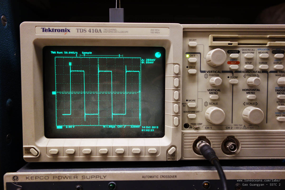
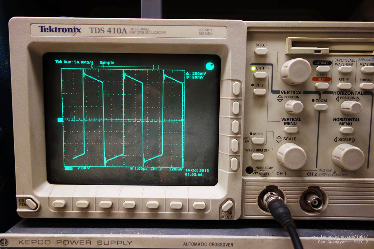
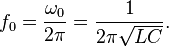
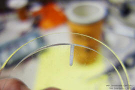
Care must be taken when making your own
GDT. It needs to be accurately wound on a suitable ferrite core,
and isolated properly. The
best way to test if a core is suitable is to wind a few test
windings on the core, connect one end to a signal generator
(square wave) at the planned frequency of the coil, and scope
the outputs with an oscilloscope to make sure the signals come
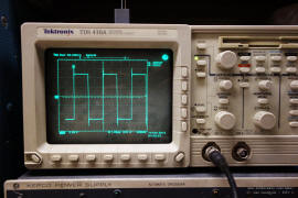
out looking more-or-less square. In the above photos, the left
photo shows the scope when directly connected to my signal
generator. The right photo shows the output of my completed GDT.
Note that you cannot simply use any toroid you
find as a GDT! It needs to be a suitable ferrite material (no
iron cores), and the only reliable way to make sure it will work
is to do the test I did above, so you do need a scope and signal
generator at the very least.

I am driving the primary of my GDT
with +-12V. However, in order to turn on the gates of my IGBTs
as quickly as possible, I want to drive them at a higher voltage
of 18V. Hence, my primary of the GDT is wound with 8 turns and
the secondaries wound with 12 turns to provide a 1.5V step up.
Scoping with the oscilloscope shows that it works (see photos
above, noting the units)! Above is a photo of my completed
GDT.
To protect the gates, it is useful to add
something like 22 or 33V zener diodes / TVS across the gate and
source to protect the gate in the event of any voltage spikes. I
have omitted them in my design for this coil.
Frequency Generator
The frequency generator drives the frequency of
the primary coil and it should be able to be adjusted to run at
the resonant frequency of the secondary coil. The most obvious
way is to use an external frequency generator, such as a TL494,
which was done on the first generation SSTCs around the start of
2000.
However, this is quite ineffective in practice. When a spark is
produced at the top of the secondary coil, it has its own
capacitance and this decreases the overall resonant frequency of
the circuit. This puts the coil out-of-tune.
A common method of use simply calls for a
vertical wire being places a few centimeters from the coil,
around 15cm in length. This acts as an antenna, picking up a
small sinusoidal current. Using schottky diodes (diodes with a
low forward voltage drop, and hence, fast) to clamp the signal
to ground and +Vcc, so we do not fry our drive chip (Germanium
diodes like the 1N60 are fine also), we obtain a square signal
to the input of our driver. Hence, the coil is self-tuning. This
method represents the easiest and most convenient way and is
what my SSTC 1 uses. The disadvantage of
this is the somewhat finicky positioning of the
antenna.
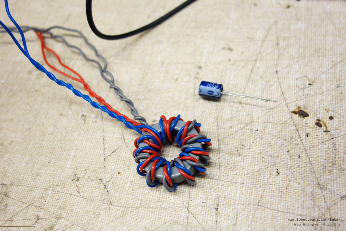
Another method is obtaining feedback using a
small current-transformer on the secondary coil. This is
constructed by wrapping around 50 turns of wire on a small
ferrite core with the secondary wire going through this ring on
the ground side. Care must be taking to ensure the right
phasing, which is simply done by reversing the direction of the
secondary wire if the phasing is wrong. I find this to be more reliable than the antenna, and
removes the need for a fragile wire sticking out of the driver.
Thus I have employed the use of secondary current feedback.
Likewise, schottky diodes clamp the output. The output of the
current transformer is fed through two logic inverters (74HC14
or similar) which cleans up the signal to the Mosfet driver.
There are other methods also but they are beyond
the scope of this page :-)
Interrupter
The interrupter can be any circuit which gives a
1-bit signal (on or off) to the driver. There are many ways this
can be implemented (or as mentioned, not implemented at all).
Perhaps the most popular way is using two 555-timers together,
one running in astable and one running in mono-stable. By
varying the resistors connected, one can vary the pulse-width
and the frequency. See my SSTC 1 which
uses such an interrupter for more details. The output of the
interrupter is usually some kind of logic signal (usually 0V for
0 and 5V for 1), and this can be fed directly into our drive
chip's enable pin.
However, especially when running large powerful
Tesla Coils (where the spark length can make the coil very
dangerous to be near), it is often a good idea to control the
SSTC from afar, necessity the use of an external interrupter
powered by a battery with a wire leading to the coil (a shielded
RCA cable is usually used). For an even safer operation (and
greatly reducing interference from the RF produced by the Tesla
Coil), fiber optic can be used to transmit the
signal. This way, the interrupter can be completely electrically
isolated from the Tesla Coil. This was implemented in my DRSSTC 1
using a standard plastic fiber optic cable, and my
DRSSTC 2 using a 62.5um multi-mode ST
fiber-optic interface.
For simplicity, elegance and compactness, I have
decided to integrate the interrupter directly inside the SSTC
this time since it will be in a shielded box. I have also used an ATTiny85 micro-processor to
produce the interrupter signals instead of a standard 555
timer. This saves me a bunch of space on my PCB since instead of
having two 555 chips and a bunch of capacitors and resistors, I
only need one 8-pin microcontroller! Two potentiometers make a variable 0 to 5V output, which
feeds into the ATTiny's ADCs. This voltage is read and allows me
the control the Pulse-Width and the Frequency, from about 1Hz
to 254Hz, with a pulse width of around 10% capped at 1.5ms (user
adjustable).
Two of the ATtiny's pins are used to measure
voltage from two potentiometers. These have a 10-bit precision
(out of 5). Using the values, I scale the pulse-width and the
frequency. One output goes directly to the UCC mosfet driver via
a 5k resistor, and another output simply lights an indicator
LED.
Construction
2013
Secondary and Primary Coils
Secondary Coil
In SSTCs, there are a few things to focus on when designing the secondary coil - we want
to have good coupling but not too much so that arc-over (from
primary to secondary or racing sparks on secondary) occurs,
and we want to increase our primary inductance to reduce
magnetizing current (but not too much since more current = more
sparks). The equation below gives L for a solenoid.
L = inductance in henries (H)
μ0 = permeability of free space = 4pi × 10^−7 H/m
K = Nagaoka coefficient
N = number of turns
A = area of cross-section of the coil in square metres (m^2)
l = length of coil in metres (m)
As a result, most SSTCs have 'short' secondaries, i.e. have a
small aspect ratio of about 1:1.5 to 1:3 (versus 1:4 to 1:6 for normal SGTCs)
and cylindrical primaries (good for high coupling). Additionally, they are usually quite fat
in diameter (this increases
primary inductance because the primary is usually wound as a
tight coil around the secondary coil). From the equation of
Inductance of an air-core coil as above, we see that increasing
the turns increases L to the square, and increasing the diameter
of the coil also increases the inductance by the square (since
area increases by the square of linear dimension).
Additionally, we want to drive our primary coil at a suitable
frequency - too high and we run into problems with our inverter
transistors since they do not like being switched too fast. Too
low and the size our our coil becomes physically too large.
This is a run-through of how I designed my secondary coil.
First, I chose my frequency to be in the ballpark of 250kHz. If
you recall the brief analysis in transistor selection
above, we found that we should keep below 222kHz as a rule of
thumb. However,
making the resonant frequency too low requires a physically
larger coil, so a balance needs to be made... Next I knew I had some extra PVC pipe in the 3.5" dia size. I also had a bunch of 34AWG wire on hand, which
occupies about 159 turns per inch. With a winding of 7 inches
(or a 1:2 ratio), I
get roughly 1100 turns. This gives me a resonant frequency of
371.27kHz. Adding a 8" by 2" toroid on top, I drop the resonant
frequency down to around 251kHz. A winding of 6 inches gives
272kHz. Hence, I can simply wind the coil for about 6 to 7
inches with AWG34 on a 3.5" secondary and add a small topload.
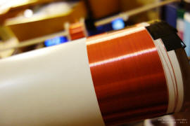

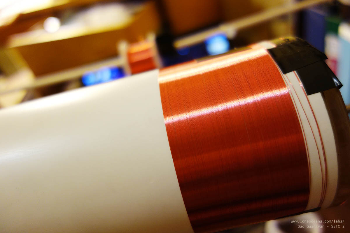
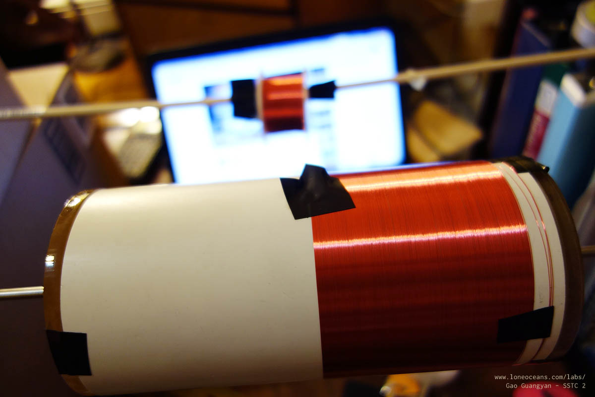
With the calculations done, I proceeded to wind the coil. I
wound enameled copper magnet wire (34 AWG) on a 7 x 3.5" PVC tube for a length
of 6.25". This was done by hand as shown above, and took
just about an hour and a half with short breaks in between. The
reason why coilers use magnet wire is because of its thin
insulation which allows us to get as many turns per unit length. With a 98% fill-rate, this should give me about 970
turns. Together with an 8 x 2" aluminium toroid, JavaTC
gives me a calculated secondary resonant frequency of 256.99kHz
with a secondary Q of 168.
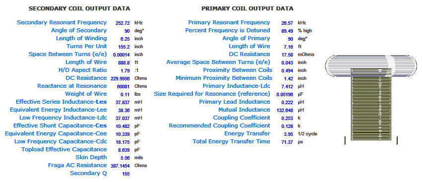
Here is a screenshot of my
JavaTC simulations. The results are from a 3.5" x 6.25"
secondary winding of AWG 34, giving me about 972 turns for about
98+% fill, with a 10 turn secondary 3.7" x 1.25" x 10 turns of
AWG 14, and a 8" x 2" toroid. Notice adding the
primary coil does change the resonant frequency and other parameters. It also
shows (to-scale) what the final product will look like!
*update - new primary coil made, see below for more details *

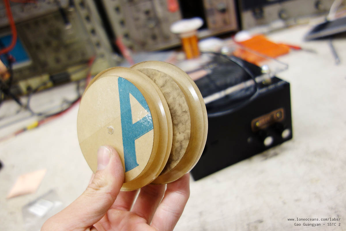
Finally, acrylic discs were cut and glued together to
form endcaps, which were then affixed to the secondary coil with
two small 2-56 screws per cap. Finally, the coil was given
several coats of oil-based polyurethane varnish. I used Minmax Clear Gloss
polyurethane, but any type of varnish should work fine.
Remember that several thin coats are always better than one
thick one (and it dries a lot faster!).


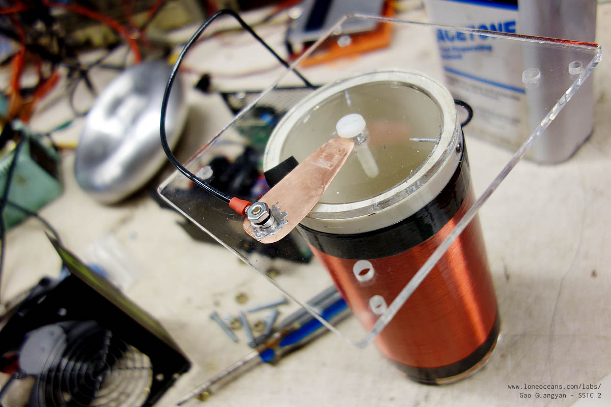
Three holes per side of the secondary coil were drilled and
tapped to accept 2-56 screws, which then hold the end-caps in
place. Finally, each end of the wire was terminated by soldering
it onto a short copper strip taped onto the end caps. The last
photo in the top right shows how I affix it to the base plate,
with a grounding strip connecting the ground wire to the
secondary coil. The total resistance of the entire connections
from topload to mains ground is just slightly over 200 Ohms.
Primary Coil
For the primary coil, this is made by simply winding a few turns
of thick wire (>=14AWG) at the base of the secondary. For a
normal SSTC, we generally want good coupling and many turns to
reduce magnetizing current. Around 6 to
9 turns should do the trick, but turns up to 20 are also common. Experiment around and see which
produces the best result with a suitable steady-state current
and minimal heating of the inverter.
One important note is that it is important to add a DC-blocking
capacitor in series with the primary coil across the inverter
output. In half-bridge configuration, two capacitors can be used
in series across the + and - of the bus rails, with one end of
the primary connected to the bridge output and the other to the
middle of the half-bridge. This capacitor should be a small
fraction of the bridge impedence (Vout / Iout), and should be
set to be well above the resonant frequency. Typical values
range from 1 to 6.8uF, and are typically film capacitors.
Note that the reactance X_c of the capacitor is inversely
proportional to the capacitance, so the fairly large DC-blocking
cap (vs say a resonant capacitor for DRSSTCs which are on the
order of tens of nF) has relatively low reactance. The DC
blocking cap comes from switch-mode power supply designs, where
saturating a transformer can destroy the transistors due to high
currents. Likewise, without the capacitor, if one transistor
latches on for too long, this causes a short between
the bus capacitors through the transistor, which can lead to the
potential death of your bridge. Especially for half bridges, any
DC imbalance can also add a DC bias current without the
capacitor.
That said, many people have built coils without the DC-blocking
cap, and it is not necessary especially for small
coils. However, they can save the day in some unexpected
circumstances and are relatively cheap, so it is prudent to add
one. I've used a 4.7uF MKP metalized polypropylene film
capacitor in series with my primary (you should use a good
quality polypropylene capacitor - I used 4.7uF because I had one
on hand, but any capacitor around this value should be fine).
05 Nov 2013
* Updated Primary Coil *
If you browse around some of the earlier photos of the coil, observe
that it used some thin blue wire (7 turns). I found out that
while this produced good sparks up to 8.3", the coupling seemed
to be a bit too high causing the occasional
secondary-racing-sparks problem especially if a sharp breakout point was
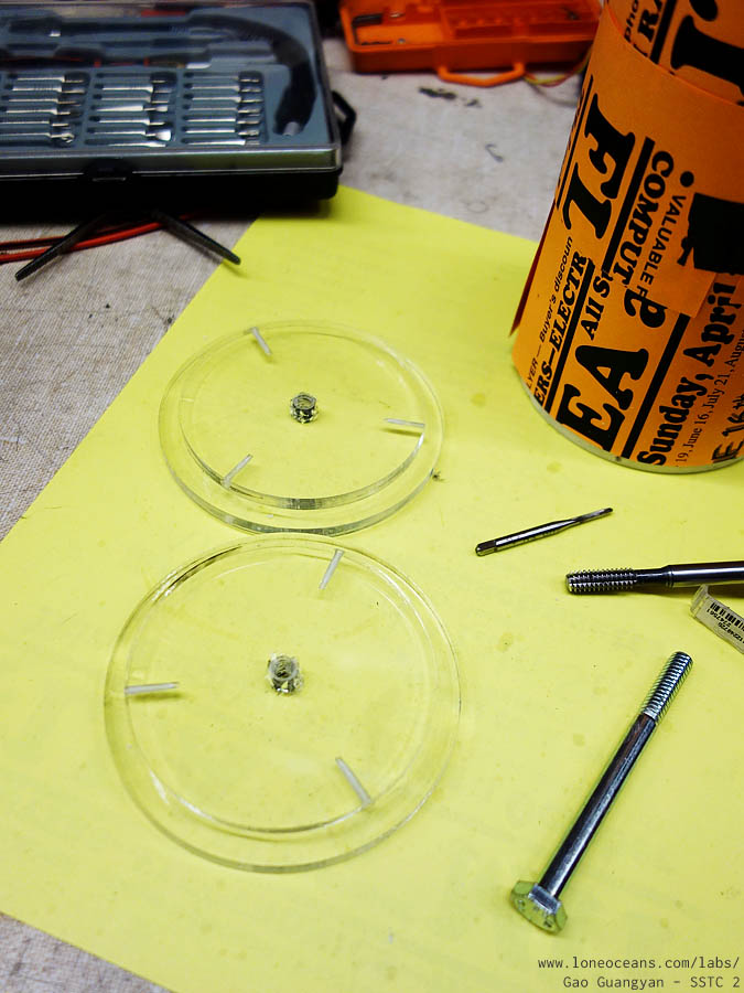
not used. So I decided to build a slightly better primary coil.
I designed and laser-cut some acrylic holders for the primary
coil so it formed a structure about 4.56" diameter around secondary
coil. This was placed slightly under the beginning of the
secondary coil and uses 14 AWG wire for 6
turns giving a winding height of 0.65".
JavaTC returns a coupling of around k=0.25 or so (full results
shown above), with the primary inductance of 7.412uH. The
secondary has a resonant frequency of 252kHz. The photo
below shows the new primary supports! For reference, the old
primary had a coupling closer to 0.28 and inductance of ~8.5uH.
From these values, the reactance of the primary can be
calculated to be X_L = 2pi * f * L = 11.74 ohms. Since the DC
blocking cap presents a low reactance (we'll ignore it) and
assuming the primary resistance to be negligible, with a 169V
(120 * sqrt 2) peak to peak square wave across the primary, we
should see a peak current of about 14.4 Amps! This
increased current compared to the old primary should give larger sparks.
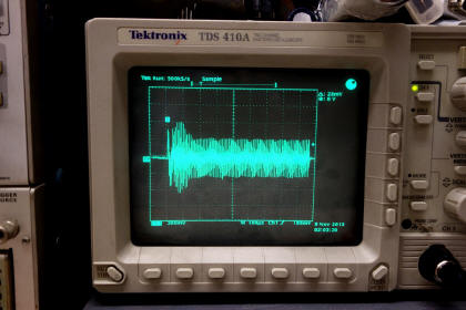
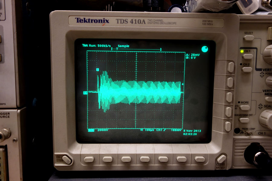
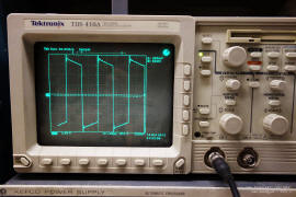
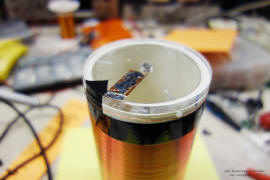
So how well does theory match up with the real world? I hooked
up a 300 turn current transformer (terminated with a 47R
resistor) and measured the current of the primary with an
oscilloscope (photo above). From the waveform, the steady state
current shows a 2.23V max (this was a 10x probe). This means a current of 0.0474A
through the resistor, or 14.23A through the primary - it
matches what we expected from our calculations.
Note that the peak current goes up to about 30A (27.9A as seen
in this waveform) before streamer loading on the secondary, but
the steady state current remains around 15A regardless of the
length of the pulse width. If you recall our quick analysis in
the transistor selection part above, you can see that
this is actually within or at least close to ratings of
our IGBT (18A continuous at 200kHz) and should be able to run happily for long periods of
time :). It's always good to have a coil run within specs -
something difficult to do in DRSSTCs!
For those of you designing your own primary coils, it is good to
decide on a current you wish to run at (anything below 30A
should be
good for reliable operation or even 50A for well heat-sinked
transistors), and add/remove turns while making sure your
coupling doesn't get too high and cause racing sparks on the
secondary.
Toroid
I used to make my own toroids out of ducting and aluminium foil,
but have also had good results with hand-made foam toroids
wrapped with foil as well as aluminium ducting toroids. However,
I decided to buy a cheap stamped toroid. It measures
just about 1.9" x 8".
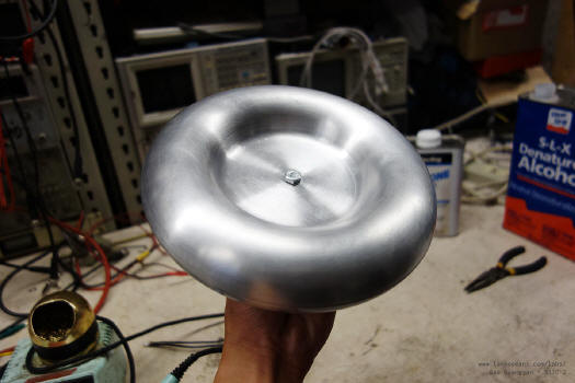
I also spent some time on the lathe sanding it to remove some
marks left over from the stamping process. This gave my toroid a
nice spun-aluminium finish. According to my calculations, the
effective topload capacitance is just about 8.3pF putting my
total resonant frequency around 250kHz (it's closer to 308kHz
without the toroid). Finally, a sharp breakout point was added.
This was simply a wire cut at an angle to produce a pointy tip.
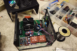
Enclosure and Box
Part of the inspiration for the project came about when a friend
of mine threw out a spoilt computer power supply unit. It came
in a nice black box with an IEC power input jack, ground connections
and a nice big fan all integrated. I decided to work within the
constraints of this box for my SSTC. The goal is to create a
very simple, modular coil which I can transport around easily
and quickly.
The box did place a constraint on how large my components could
be. One thing I had to compromise was the size of the heat-sink
for the IGBTs. To make up for this, I added two headers for which I would be able to connect two fans. This large flow
rate combined with my low duty-cycle should be
sufficient.
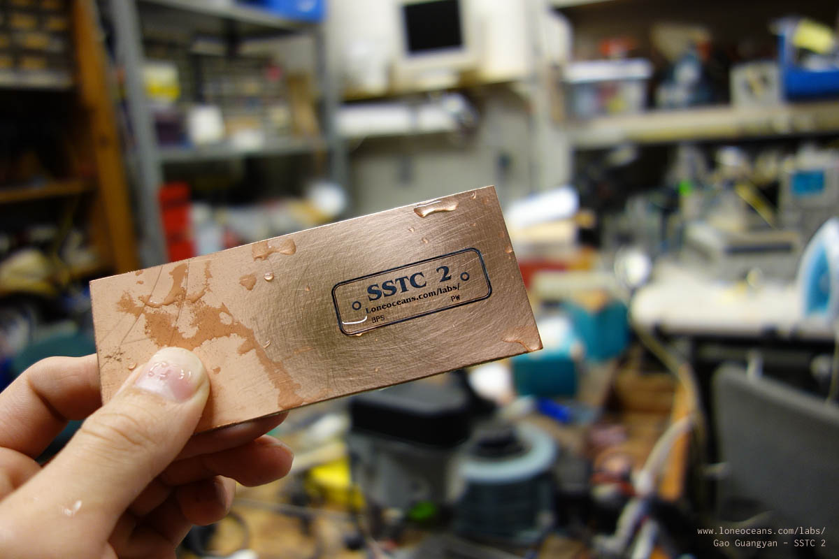
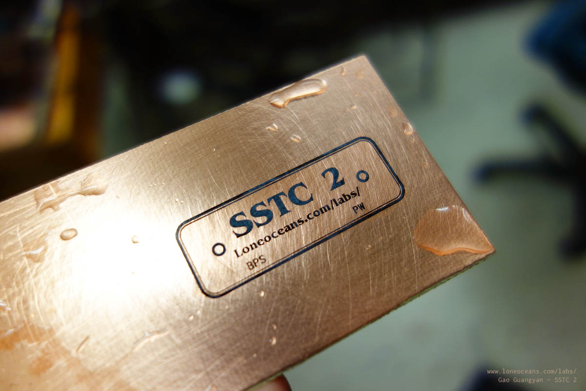
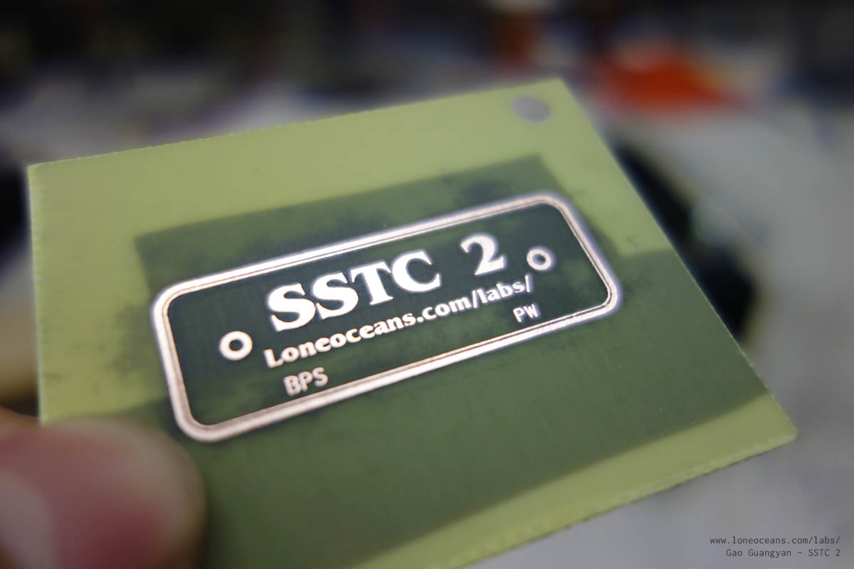
Finally, I wanted to make some sort of label for my Tesla Coil!
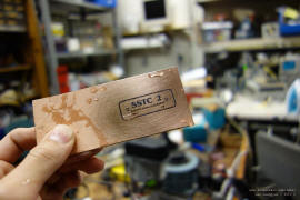
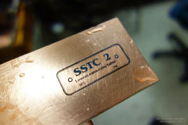
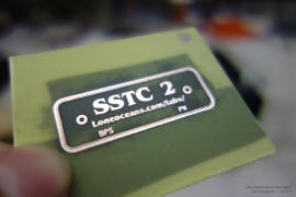
This was simply done by etching on a spare piece of PCB a little
label + the BPS and PW labels for the two potentiometers. This
turned out beautifully and the label is attached to the box via
two 2-56 brass screws. A thin coat of varnish was applied over
the label to prevent future oxidation of the copper. Finally,
note the laser-cut platform for the coil-forms, as well as the
convenient hole in the box for the grounding and primary wires
to go in to. The platform also allows intake for the big 120mm
fan which provides cooling for the whole coil.
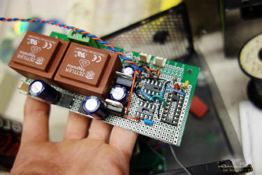
Power Bridge (Half Bridge)
My original plan was to etch my own PCB in making the inverter.
However, since this would be done in-house, it would be
challenging to make a double-side PCB, which is essential in
creating a low-inductance bridge. Fortunately, I came across some old PCBs created by my
friend Bayley. A few months ago, Bayley was working on a small
single-board DRSSTC, and had some spare old-revision boards left
over. Conveniently, the inverter section was physically separate
from the driver section. So I cut the PCB in half and used the
inverter side to mount my bus capacitors and IGBTs. This
low-inductance layout should hopefully remove the need to add
bulky film snubber capacitors and TVSs.
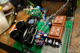
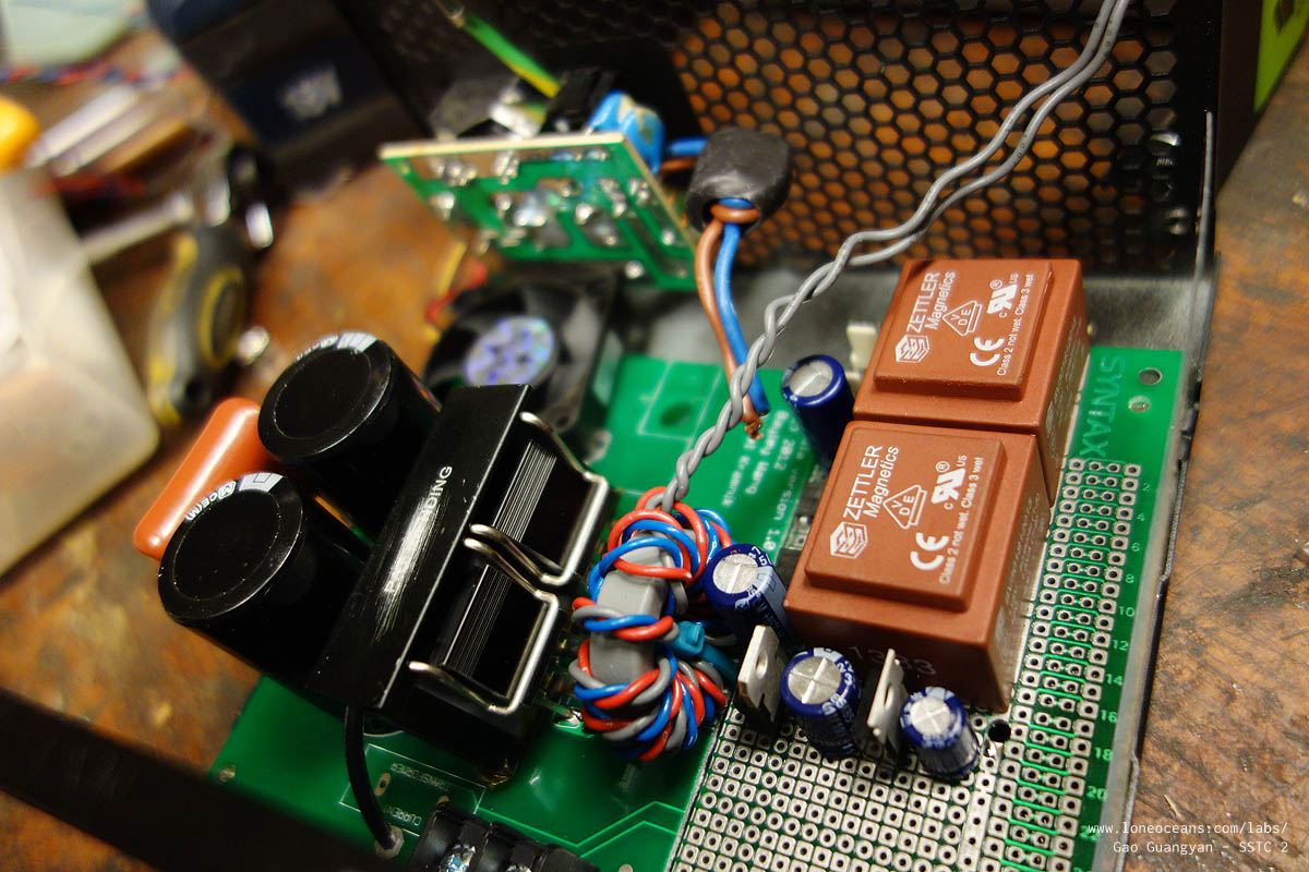
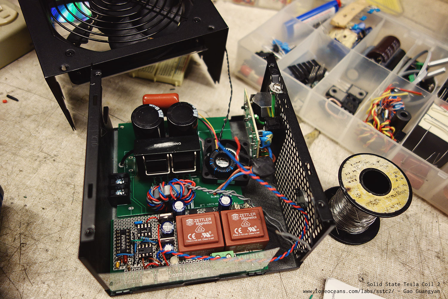
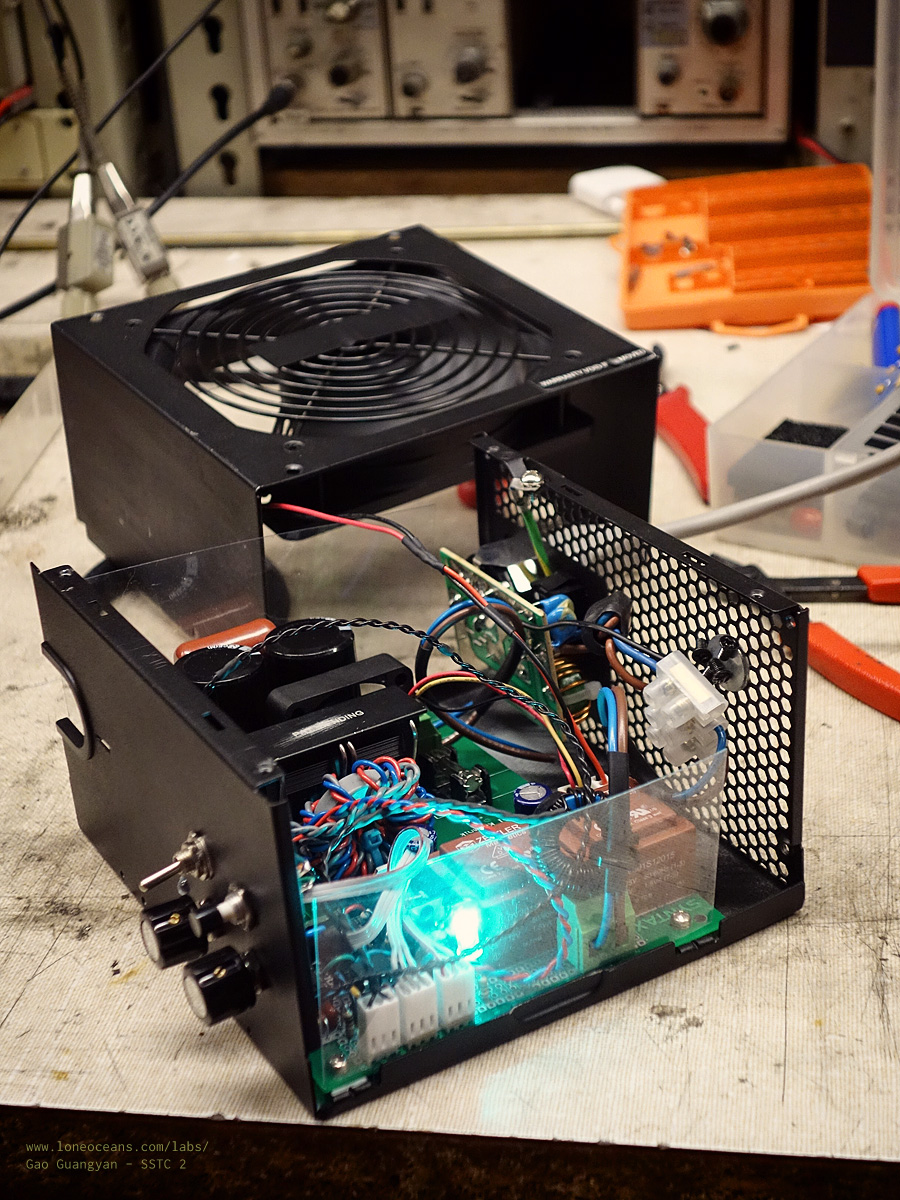
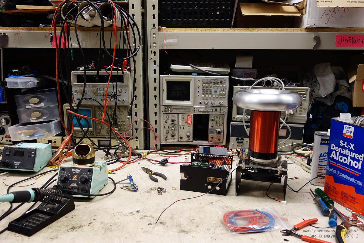
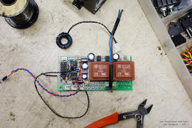
Here you can see how the layout looks like inside the
power-supply box. One side with the head-sink and the two
electrolytic capacitors is the half-bridge with the GDT
installed in place. The right side is the control circuit board,
dominated by two small 12V transformers. Everything is a tight
fit, but works out well. The heat-sink for the two TO-247
transistors is a bit on the small side, but the large fan at the
top of the box + and additional small fan inside, coupled with
my low duty cycle should help keep things cool. Remember that
the goal of this project was to keep things simple and compact,
but you should probably add a bigger heat sink for your coil.
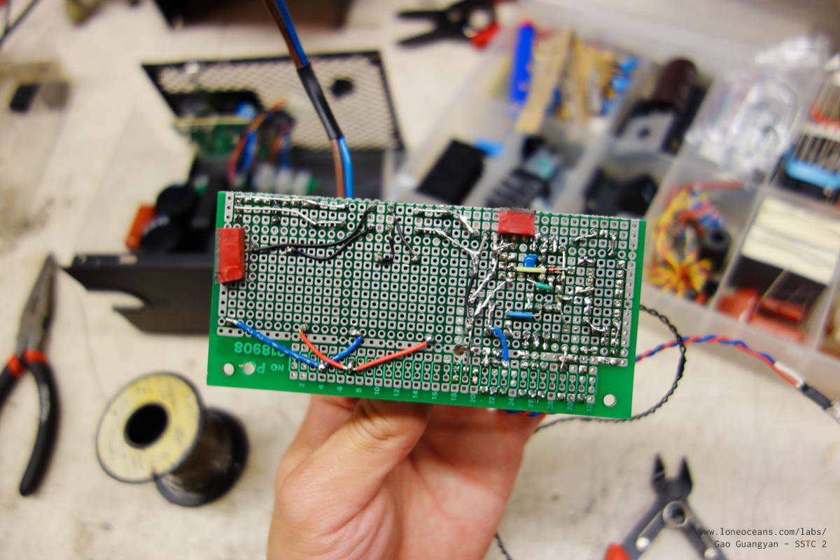
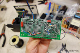
Driver
The driver circuit was simply assembled on a perf-board and
connected via wires and solder bridges. I decided not to etch my
own PCB this time, because wiring up this way should be easy
enough for a small circuit. After all, it only uses three chips -
the ATtiny interrupter, the UCC and the Hex Inverter (which could probably
be emitted)! The logic power comes
from a small 120V to 12V transformer which is full-wave
rectified and regulated via a 7812 and 7805. A generous amount
of filter capacitance was added on the logic bus. A separate
transformer provides 12V for the two computer fans used to cool
the electronics.
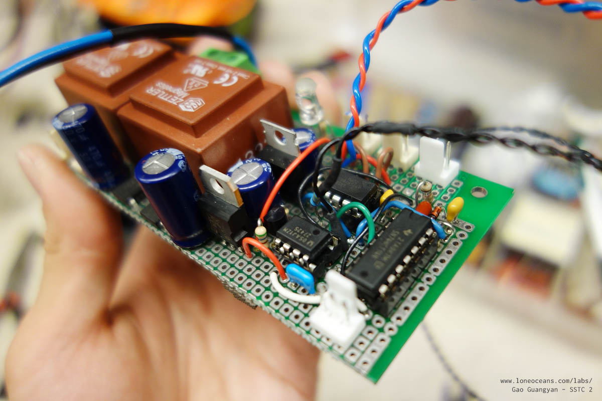
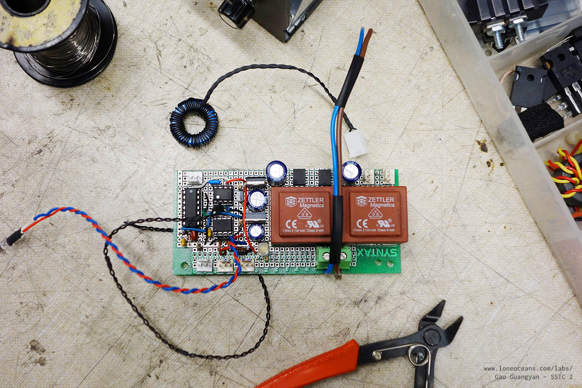
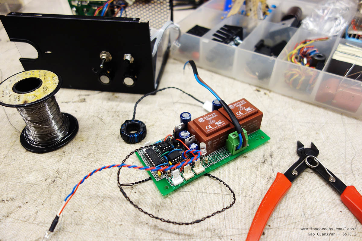
Above is a photo of the more-or-less completed driver (without
the chips yet). The bulk of the board is taken up by two small
120V to 12VAC EI30 transformers, good for supposedly 1.5VA each. The
left transformer has two 3-pin molex headers for easy
connections to the fans. Note that the output is rectified by
two bridge rectifiers and have their own filtering capacitors.
These two circuits are separate.
The other filtered 12VDC rail is regulated by a 7812 and chained
with a 7805 for my 5V rail running the ATtiny and 74HC14
inverter IC. The output of the ATtiny85 is sent to the input of
the UCC mosfet driver (via the blue resistor). The two other
3-pin headers at the top of the board go to the potentiometers.
Another header was subsequently added for secondary input to the
74HC14 for feedback. Finally, a low-voltage lock-out was also
added subsequently (yes they all fit nicely on the board).
After a bit more work, all the components are populated.

Note the two LEDs - one is directly soldered on the board and
serves as a power indicator LED. The second is connected to the
second output of the ATTiny85, and provides a visual indication of the
output of the interrupter signal. Finally, the 50-turn secondary
current transformer is also visible. The bottom of circuit board
looks a bit messy, but it works well. The circuit was tested
carefully and found to work well first time around :-) with no
problems!

The board was inserted into the case (held in place via two
screws), and plugged in. A few more
things to note here - I used some relatively thick plastic sheet
as a safely insulation liner between the bottom of the PCB and
the metal case. Also, you might
note the single pole and push-button switches installed at the
front of the box. This was meant to control the interrupter
signal, but I subsequently removed them for simplicity. Turning
the Freq potentiometer to 0 automatically turns the interrupter
off. This is all controlled via
ATTiny85 programming. Finally, yay for the Aqua LED (it really
looks a bit more green in real life)!
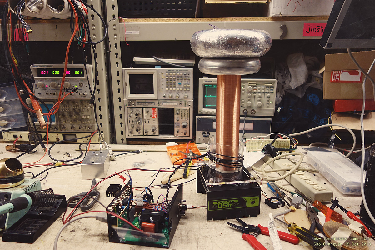
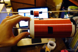
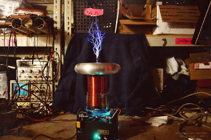
Putting it all together
With all the parts completed, it's time to put them together.
Above shows SSTC 2 with the secondary and topload all securely
in place (along with the messy workbench!). It's now time to
test the coil!
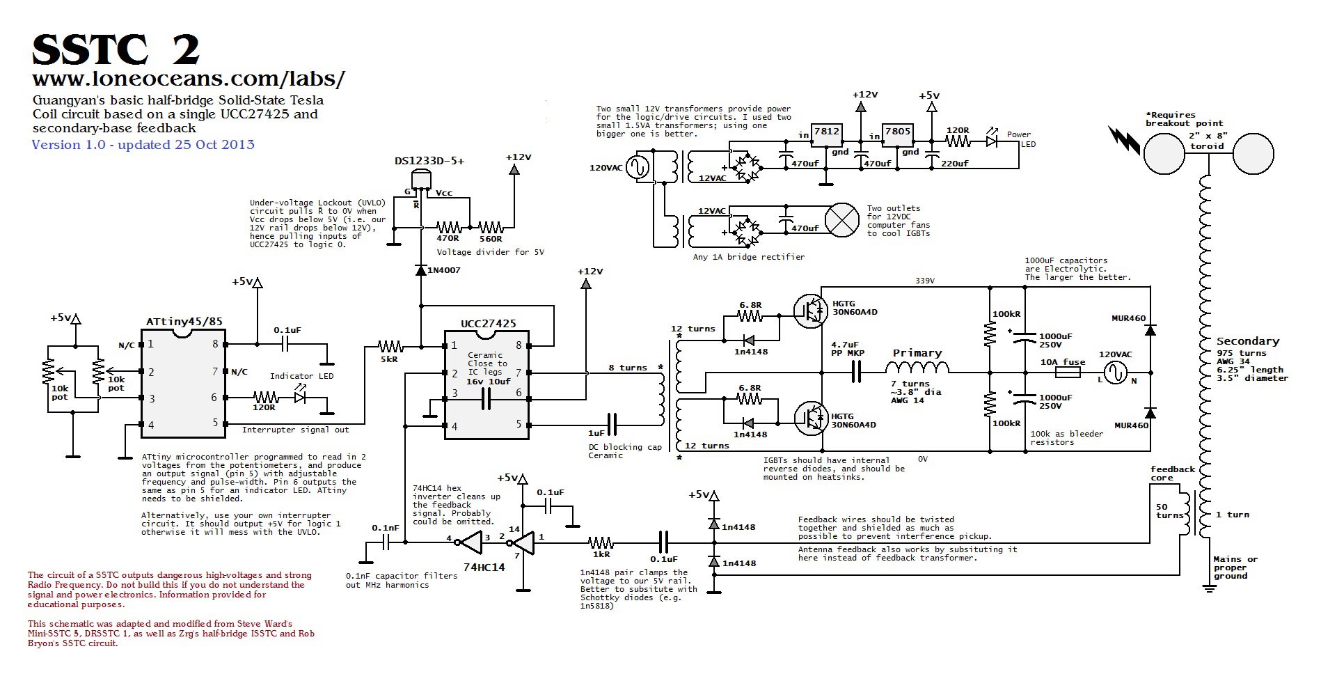
Schematic & Interrupter Code
And as a reward of reading till here, here's the schematic for
the entire SSTC 2 for your reference! I've tried to make it as
straightforward and understandable as possible, but you should make
sure you understand every component of the circuit before building it.

This schematic was modified from the original designs of Steve
Ward's SSTC 5 schematic, whose contribution to the Tesla Coil
community has been immense. The original designed used an
antenna feedback and dual UCC Mosfet drivers for the GDT, and a
555 interrupter. I replaced the interrupter with a programmable
ATtiny microcontroller instead. Finally, with more inspiration from Bayley's
and Zrg's SSTC, I replaced the dual UCCs with a single UCC
driver capable of dual invertering and non-inverting enables to
simplify the circuit even more. An additional under-voltage
lock-out is employed for safety but could be omitted.
I believe this circuit is almost as simple as it can get whilst
still being generally quite reliable. I've also added as many
notes to the circuit. The voltage regulation circuit can be
simplified with a single transformer. For feedback, you can use
any sort of feedback (antenna, secondary, etc), and the 0.1nF
filter cap can also be omitted since it does introduce some
delay in the feedback loop. If I were to put it in again, I'd
put it before the 7414 inverters directly on the output of the
CT instead.
Now the final piece of the
puzzle is the interrupter code. I've presented it here for you
to use. Feel free to edit it to suit your needs! The file is in
an Arduino .ino format and was designed to be programmed into an
ATtiny85/45 micro using the 8Mhz internal clock and using the
Arduino as an ISP programmer. Download the latest
version 0.63 here.
For those of you who no not have an Arduino, you can download
the Arduino IDE, compile the code and burn the .hex code the
normal way. If you do not have any experience with
microcontroller, you can simply build a standard 555 circuit
(see my SSTC 1 page for details), or any other interrupter of
your choice.
If this project has been helpful in any way, I'd be happy to
hear from you and the results of your coil!
Enjoy and be safe!
Results
Mid Oct 2013
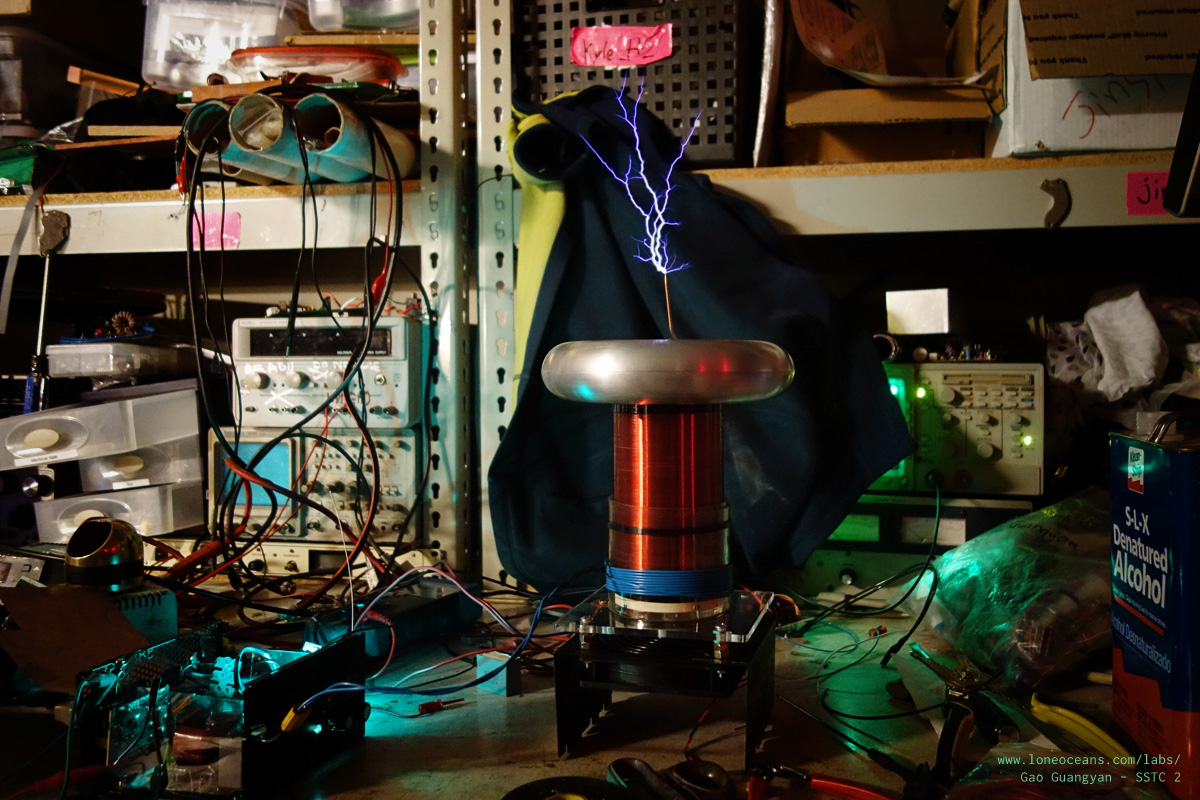
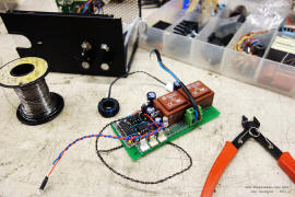
Testing the Coil - Preliminary tests
With all the components done, it was time to
test the coil! I was still not done with my actual secondary
coil yet, so I used a temporary secondary coil lying around the
workshop. It measures 12" x 2.5" with 34AWG. A 6-turn 3.5"
primary was used with a 6x1.5" + 7 x 2.5" toroid, bringing the
resonant frequency to about 300-350kHz.
It is prudent not the test the coil at full
power first, so I ran the coil off a DC power supply. Notice the
two switches in front of the control box, which I used to
connect/disconnect the ATtiny85 output from the UCC. It turned
out to be a bad idea because the UCC input goes to high when it
is not connected = CW mode, but can be easily solved by
connecting to ground via the switch. Instead, I removed the
switches and changed my programming of the ATtiny85 to turn-off when
the BPS knob is turned to 0. This simplifies the control of the
coil. The coil starts to oscillate at around 20VDC, and I tested
it up all the way to 90VDC on the bus. The coil made small
sparks and generated a very strong RF field around the coil,
which can be felt in terms of burning-tingling sensations when a
metal object in the vicinity of the coil is touched. The coil is
working!
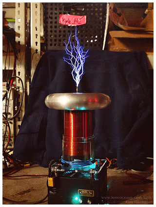
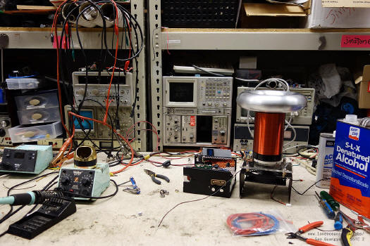
First Light!
The first time a Tesla Coil makes sparks is
generally regarded as the 'First - Light', and is considered a
milestone event by Tesla Coilers! After first-light, usually a
bit of tuning will need to be done, but the fact that the coil
makes sparks is generally a good indicator that the main
components are working correctly. This photo records this
moment!
Here, the coil is running at a relatively low
BPS (around 50 - 100Hz), with a pulse-width of about 400+us. The
input voltage is just about 80+VDC across the bridge, which is a
lot less than the 340VDC it will see eventually. Here, it just
about makes 2.5 - 3" sparks. Also, the coil is running with a
separate secondary from the one I will be using (it's a 12" x
2.5", 34AWG coil with a 6-turn primary on a 3.5" form, with two
small toroids, bringing the resonant frequency to around
300+kHz). During this test, my secondary coil was still not
completed yet.
Testing the coil - with actual primary and
secondary

After the varnish on my actual secondary coil
had dried, it was time to test it! As before, I began by winding
10 turns of wire as the primary coil around the base of the
secondary (note the PVC sheet in-between as insulation), and
connected my bridge to a 0-100VDC power supply. The coil sprung
into life easily, but it was clear that when I raised the
voltage over 80V, I started to get skips (i.e. the interrupter
would send a signal but the coil would not oscillate).
This made me try various techniques including
adding more feedback turns on my secondary feedback transformer,
but it did not solve my problems. As a last ditch attempt to
figure out what was going on, I remove the secondary feedback
and use a bare wire antenna - this worked perfectly!
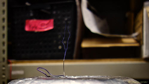
However, notice in the setup above that my coil
was running with the electronics outside. It turned out that the
ground wire from the base of my secondary to the control box was
picking up interference from the primary coil of my Tesla
Coil, causing it to give unreliable feedback. This makes
sense because above a certain threshold of voltage in my
primary, the current will be large enough to produce significant
interference in my ground wire. This problem was solved by
putting the ground wire inside the grounded case. The coil
then runs very happily off secondary base current and is what I
use in my final design.

I then switched to a variac for input to my
bridge, and slowly cranked up the power. Above around 100VAC in,
I started to get small flash-overs on my secondary coil -
hinting at [1] Insufficient insulation, [2] too much coupling
and [3] some slight asymmetry in the coil. To solve [1], I added
a second layer of insulation using an acrylic form. For [2], I
reduced the number of turns from 10 to 7, and for [3], I tried
to make the coil more symmetric. Ideally I'd have a bit more
spacing between the primary and secondary coils.
With all this done, I assembled everything back
together into the case and tested it at full power. The coil
works and performs admirably!
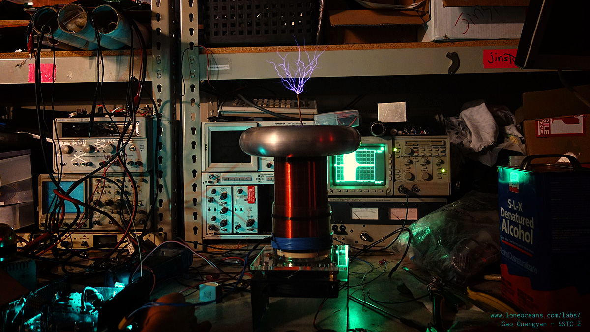
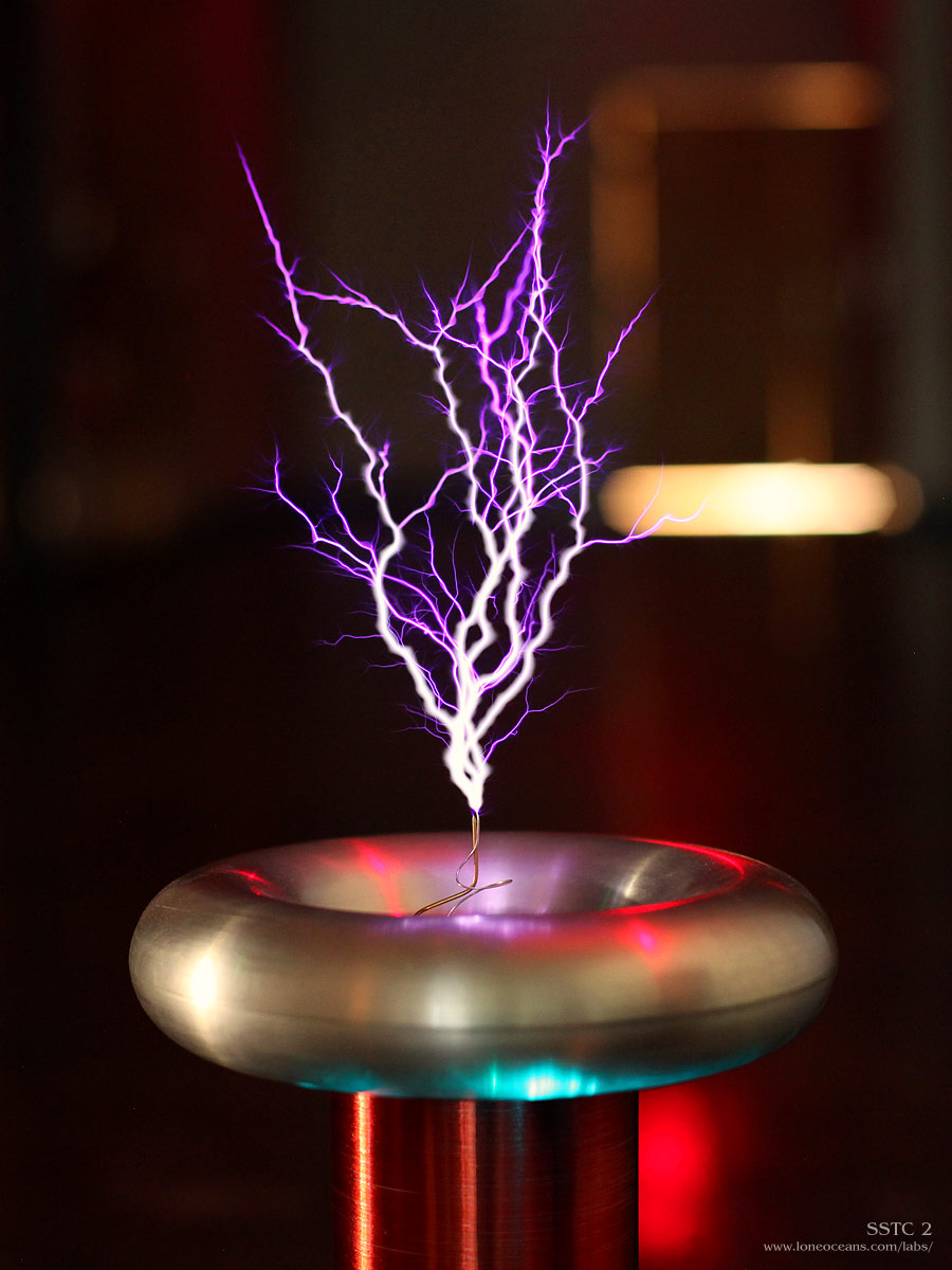
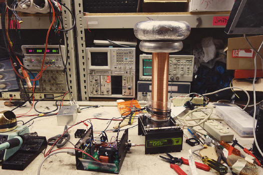
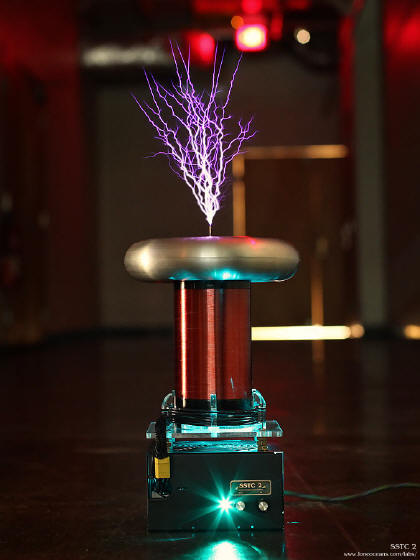
Results
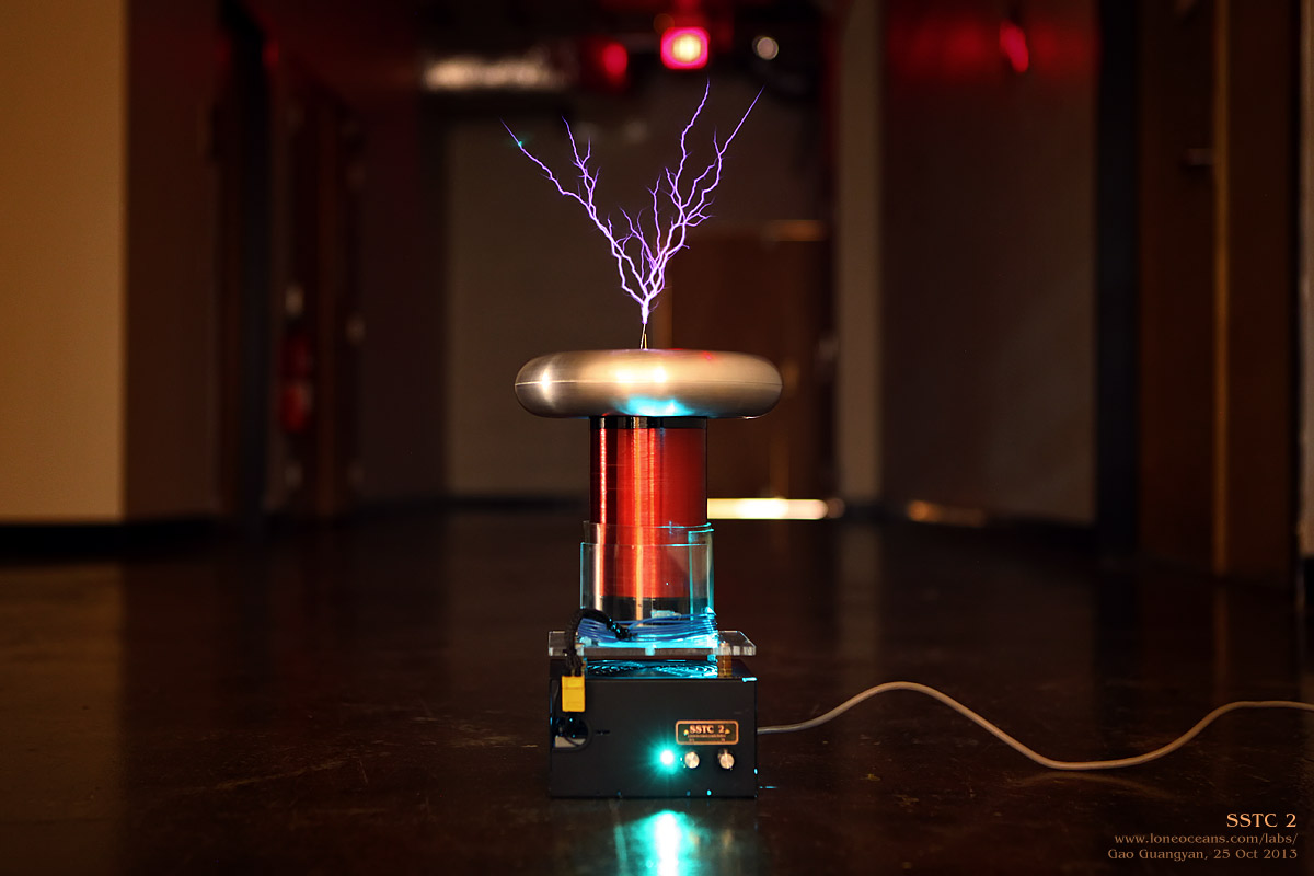
I'll let the photographs do most of the talking!
Above shows the coil just after being assembled
together. It makes just over 7.5" sparks to air, which is not
bad considering the secondary winding is only 6.25 inches. Right
now the coil's interrupter runs from 1 Hz to ~500Hz with 1000us
on-time max and a 20% max duty cycle. The photo above shows the
coil running at 1000us pulses (120VAC input).

I'm glad that the coil came together quickly and
as planned and I'm happy with the performance. I should be able
to push even bigger sparks but running this at higher voltage,
but the goal of the project was the make a small, reliable
demo-coil in a weekend. The project actually wound up taking 2
weekends, but I think it was worth the extra effort to make
things look nice. It also met all my design goals resulting in a
compact, portable and reliable Tesla Coil suitable for demos.
Here, SSTC 2 is making around 8" sparks with 1000us on-times.
Right now there are no plans to made additional
modifications to the coil except for maybe tweaking with the
interrupter code and perhaps lowering the overall duty cycle to
10% max but increasing the max pulse width to 2ms. Till then, I
hope this page has been helpful in your quest to design your own
SSTC :).
01 Nov 2013
I made a few small tweaks to the interrupter
code. The coil now runs from 1 to 254Hz and pulse-width from 0
to 1.5ms for thicker more fiery sparks. I also updated the
interrupter code which is available for download above.

I'm now happy enough to say that the coil is
done! Some final observations include that it still does need a
breakout point to breakout, otherwise the coupling seems to
become a bit too great leading to occasional racing sparks on
the secondary, but this happens quite rarely if I don't use a
sharp breakout point. All is fine with a sharp point. I believe
this is easily fixed by simply making the primary coil very
slightly wider instead of directly onto the secondary coil.
Removing one turn would also probably help. Best spark-length to
air to date is now 8.3 inches!
05 Nov 2013
Final results with New Primary Coil
As mentioned above, I decided to add some
real primary stands to reduce the coupling, and will also
allow me to remove the need for the somewhat messy plastic
wrapping around the secondary coil. By increasing the diameter
of the primary, I was able to reduce the number of turns from 7
to 6 which allows slightly higher primary current due to its
lower inductance, all while reducing the coupling for reliable
operation.

With the new primary coil, everything looks a
bit tidier and spark length is now officially just hovering
around 9 inches! It also breaks out happily without a
super-sharp breakout point with no more secondary racing sparks
and runs happily at 15A primary current.
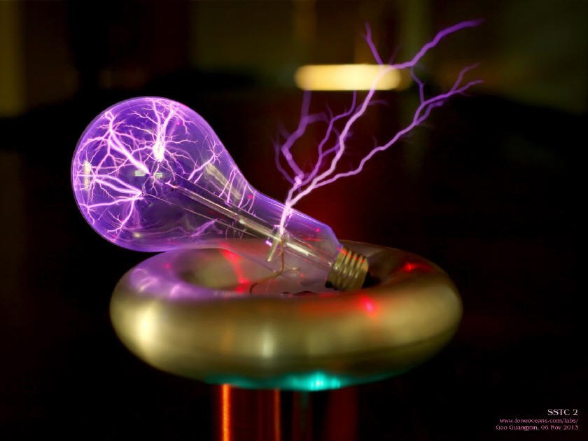
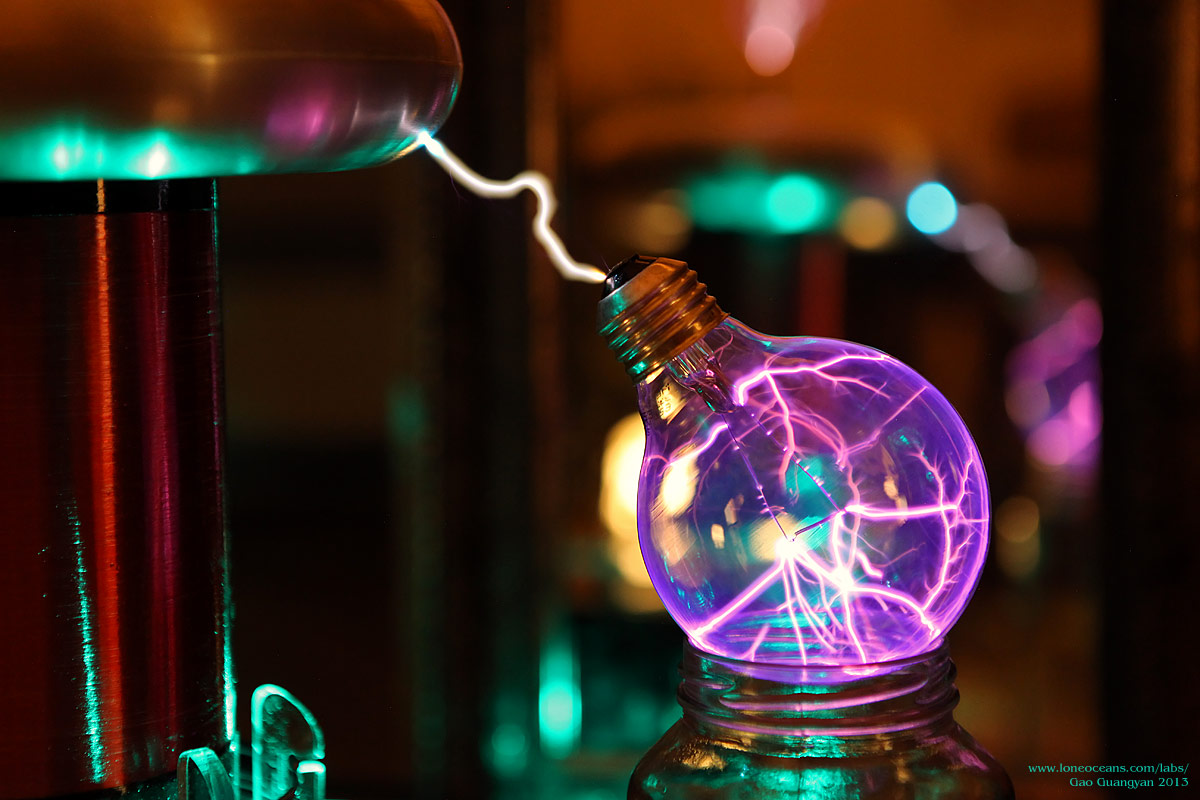
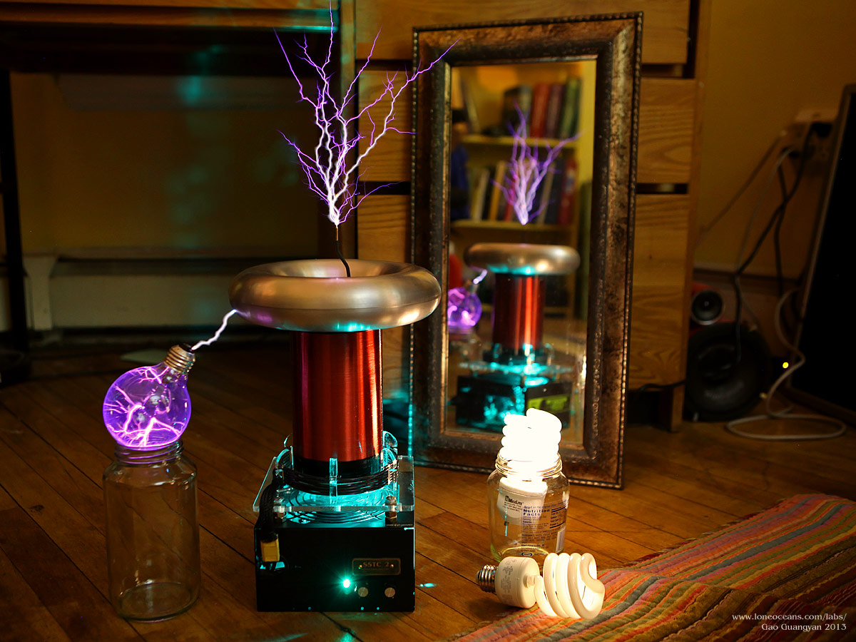
The coil also lights up big bulbs wonderfully
with some very curious spark formation in the low-pressure
environment inside a normal bulb. Finally, some overview photos
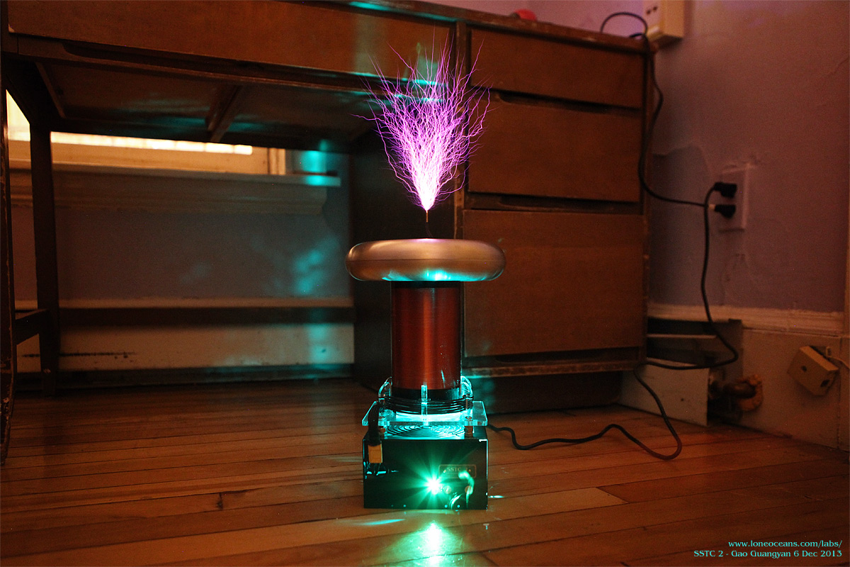
of the coil in low frequency mode and higher pulse reps.
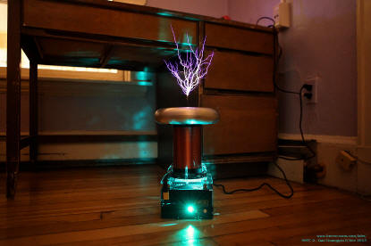

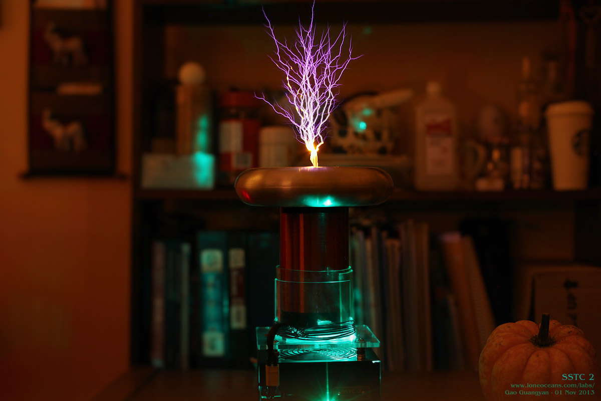
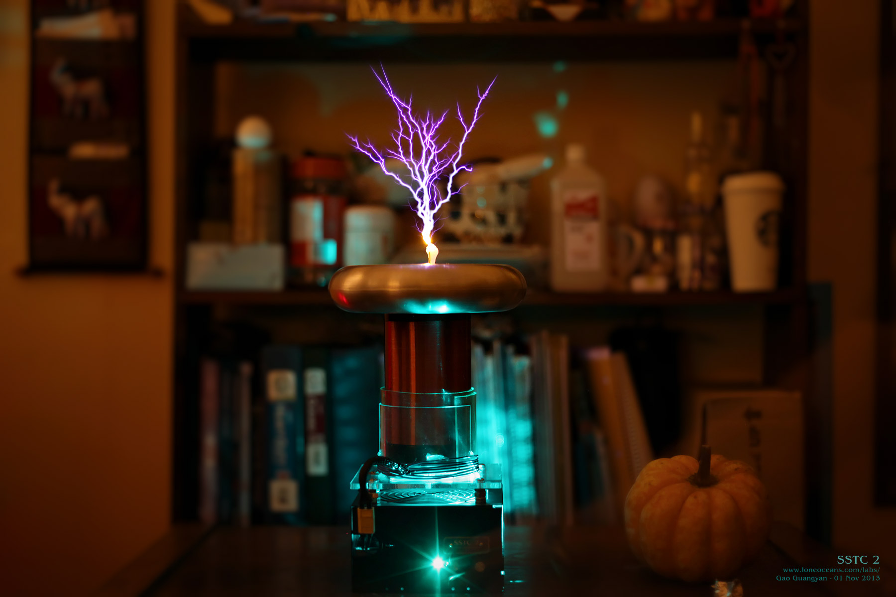
In the left you can see the coil running at low
frequency pulses at about 2Hz, 1.5ms per burst. This produces
few hot and thick sparks. The second shows operation at 200Hz,
but only a few hundred us per burst. At this power, the coil is
quite loud indeed and the sound resonates in the room and
induces significant RF in metal objects in the room, which can
be felt in terms of RF burns when touched...


Finally, the above photos shows the coil in
action around light bulbs - wireless energy is transmitted! As of now I'll
liked to declare the project a success! It's now time to move on to the next project.
:-)
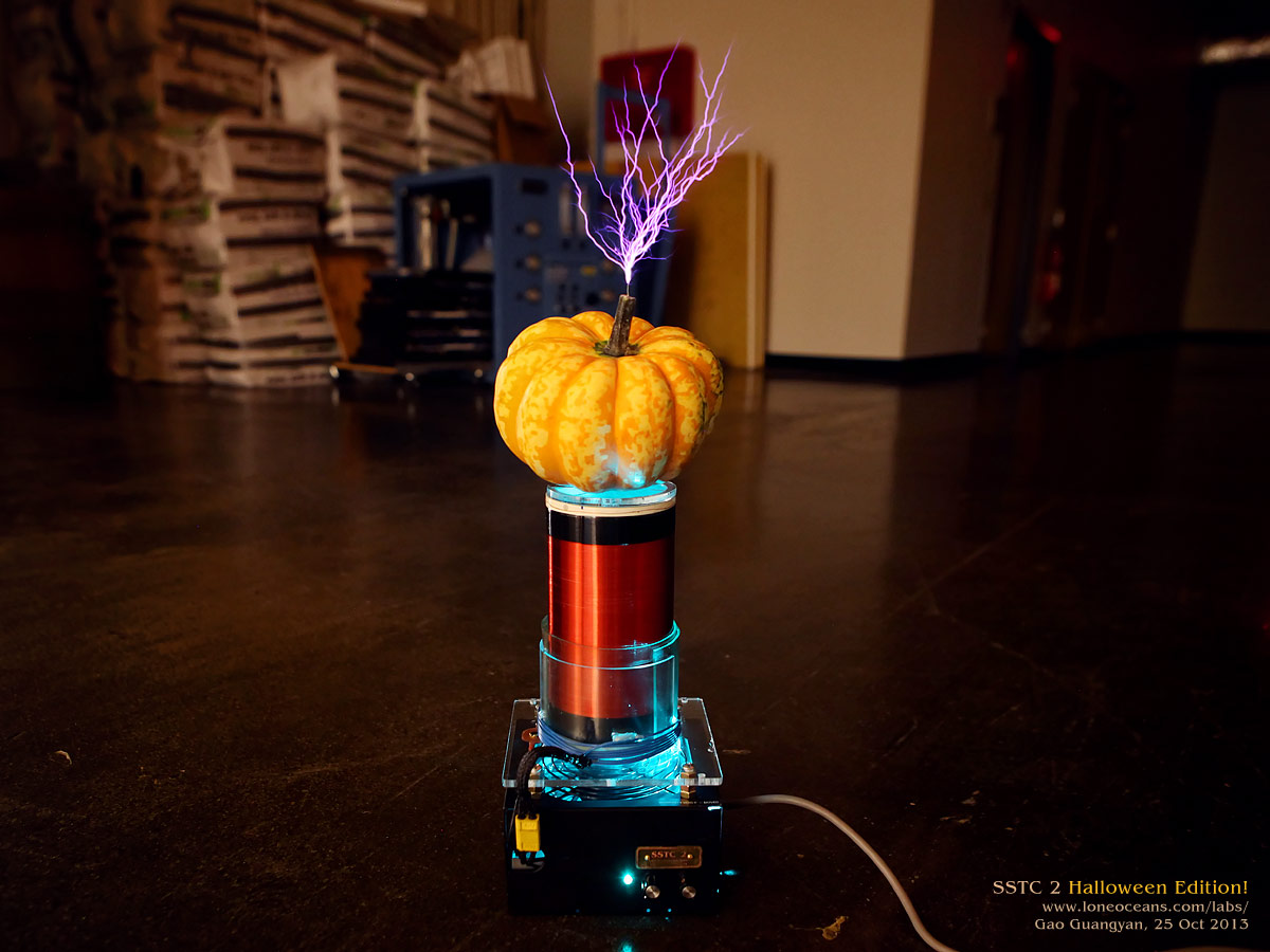
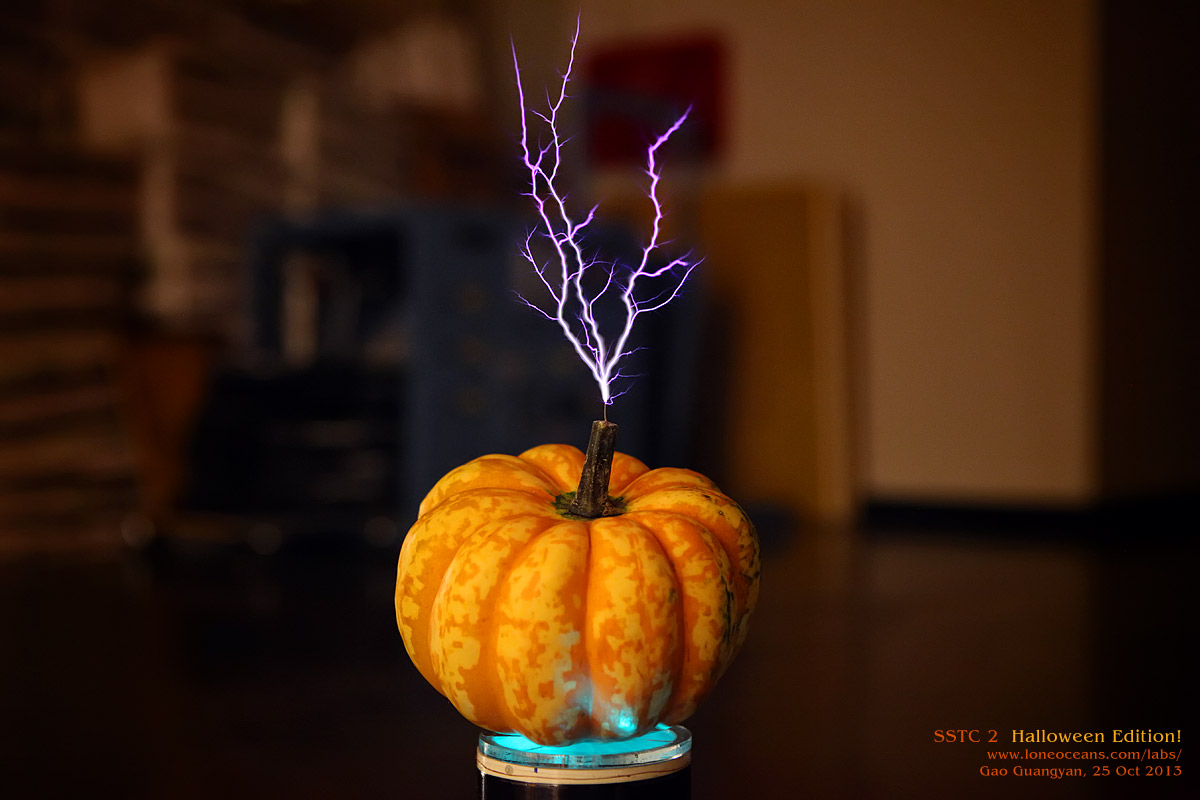
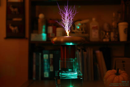
25 Oct 2013
Halloween Edition!
With Halloween just around the corner, I thought
it might be a fun idea to try replacing the toroid with a
pumpkin! I looked through a few supermarkets trying to find the
right kind of pumpkin - around 8" in diameter, and quite flat,
like a toroid. Unfortunately I didn't seem to be able to find
any around, so I wound up buying a squash instead of a pumpkin.
I then inserted two small wires at the top and bottom of the
pumpkin, with the bottom connected to the secondary and the top
as the breakout point.

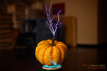
It works! The pumpkin (squash) works well as a
toroid. Hopefully I'll find a more toroid-looking pumpkin
another day. Happy Halloween everyone!
Credits
This project was inspired by the great Tesla Coils by
many other people:
- Steve Ward's one-day SSTC 5 as an inspiration for
making this coil in one weekend
- ZRG's simple half-bridge SSTC design which used one
UCC instead of the usual 3732x pair of chips
- Bayley Wang's tinyTesla project which is a tiny
900kHz Tesla Coil much smaller than this one and very cute
- The many great tesla coil and high voltage forums on
the internet which gave me valuable advice
- And everyone else who has helped me in one way or another.
More to come soon!
Back to main page
(c) Gao Guangyan 2014
Contact: loneoceans [at] gmail [dot] com |