loneoceans labs | RSSTC 3 PCB kit (temporary placeholder page)
No more SSTC 3 boards are available for sale. Please see the new SSTC 4 platform.
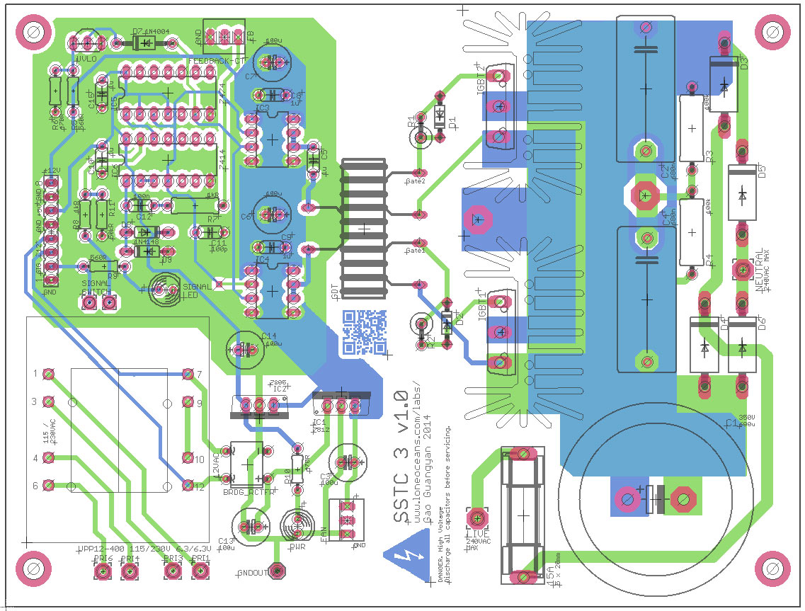
PCB Layout for the main board
The RSSTC 3 single-PCB Tesla Coil was developed as an all-purpose Tesla Coil platform for building a compact solid-state coil all one one PCB. It has several standout features:
This was the first set of PCBs I sent for fabrication for the coil. However they are expensive in small quantities. I had a few leftover boards and decided to offer them for sale since many people were interested.
This set comes with the following 3 PCBs I developed specifically for this project:
Because this set is a development board set, I cannot provide additional support for you to use the boards. However, you can see my SSTC 2 and SSTC 3 pages for a comprehensive write-up on how I used them.
Pricing
The cost is US$60 including shipping to anywhere in the contiguous USA. Will also ship to anywhere around the world (generally brings the cost to ~$70) Contact loneoceans [at] g mail [dot] com for enquiries.
Many of the parts used are quite generic (e.g. various resistors, bypass capacitors). This list is broken down into two sections - list of specific components with Digikey part numbers, and the second section with everything else you might already have on hand. Feel free to change the components to suit your needs.
Specific Parts
Common Parts
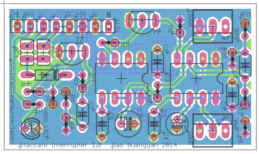
The Staccato interrupter is a straightforward build. Note the 8-pin 0.1" pitch male headers should be installed on the opposite side of the board to plug into the main board. All components are labeled and can be populated as follows in the schematic. Note the usual 2 pin jumper headers.
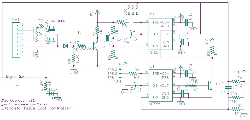
The two transistors are standard PN2222. Note the capacitor values for C4, C7 and C8. The two 3-pin headers are only actually connected to two pins as labeled. They must be connected to 20kR and 100kR variable resistors.
Finally, the standard ATtiny interrupter / fiber input board is even easier. It uses the same header pins, as well as standard 1000um plastic fiber receivers. It uses the FB123-ND (IFD95) and accepts most corresponding fiber transmitters using the 1000um plastic core fiber. The ATTiny can be programmed using code found in my SSTC 2 page. It accepts the same 20kR and 100kR potentiometers. Note that in this revision, for same direction of control for the BPS and PW potentiometers, the 3-pin headers for one of the boards must be inverted for easy swapping ability. Otherwise experiment to find out what suits you best.
Here's the RSSTC 3 board populated and installed, and running a coil with 208VAC input.
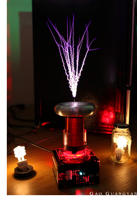
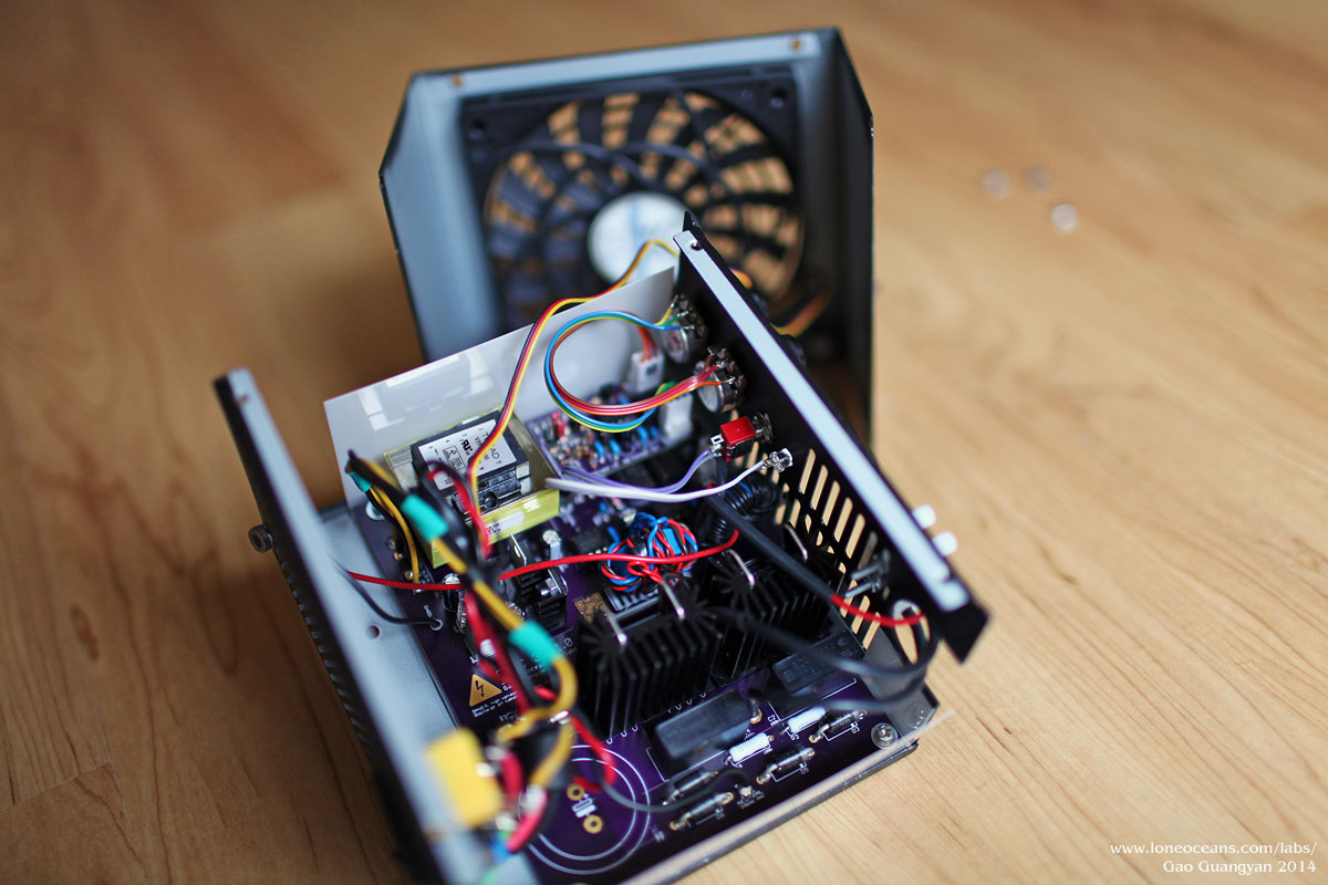
Please see my R-SSTC 3 page for more details of my build with this coil. Looking forward to seeing what you can come up with this board!
See www.loneoceans.com/labs/ for more information.
Back to loneoceans labs. (Updated June 2014)