3. The Interrupter This SSTC will feature two different forms of power modulation - through a basic and well established 555 interrupter circuit, and second via a ATMega microcontroller producing musical tones. I later build an analog musical controller for this coil which worked very well and receives input from a 3.5mm stereo input. 4. Physical Construction One of the main goals I had set for this coil was durability and portability. The design of the coil was to be elegant and modern, and yet small enough to fit into a large backpack. Construction LogThis section logs the construction of Tesla Coil Esmeralda. This is my first Solid State Tesla Coil, and I decided to construct it in a modular form. I have therefore made this log into a few sections:
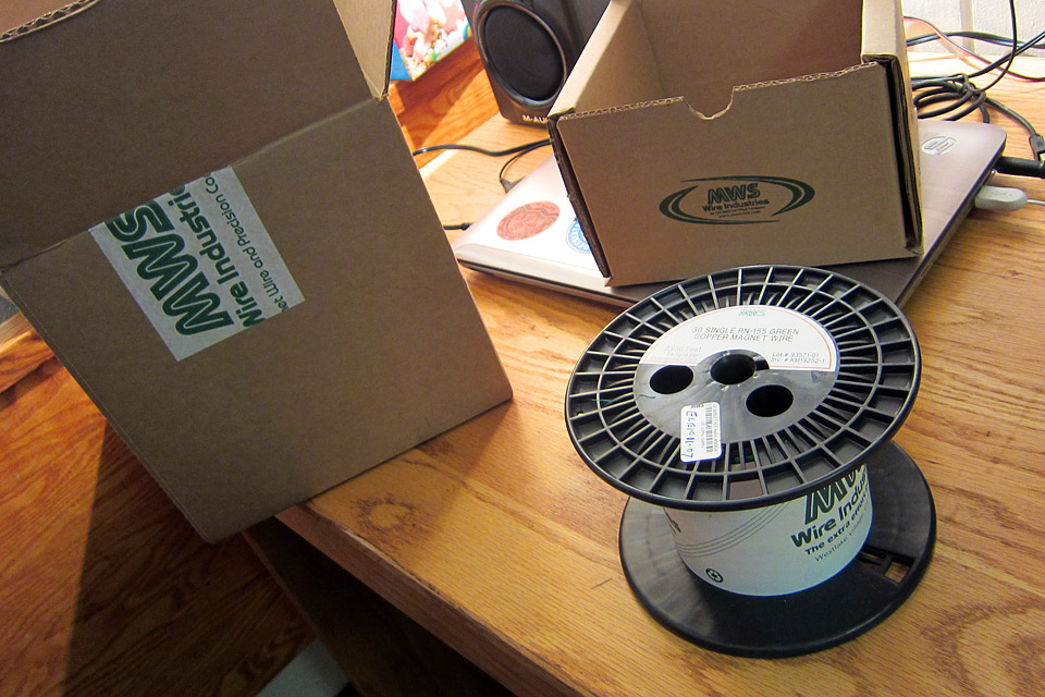
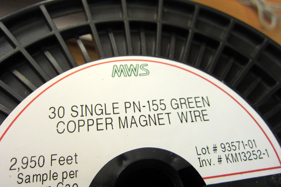
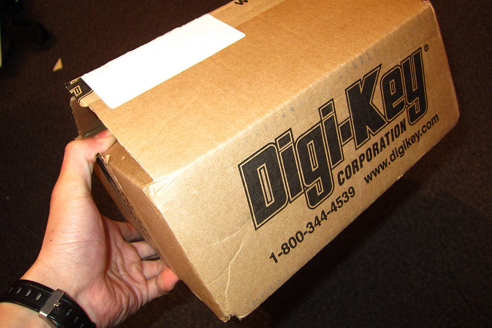
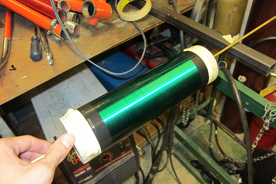
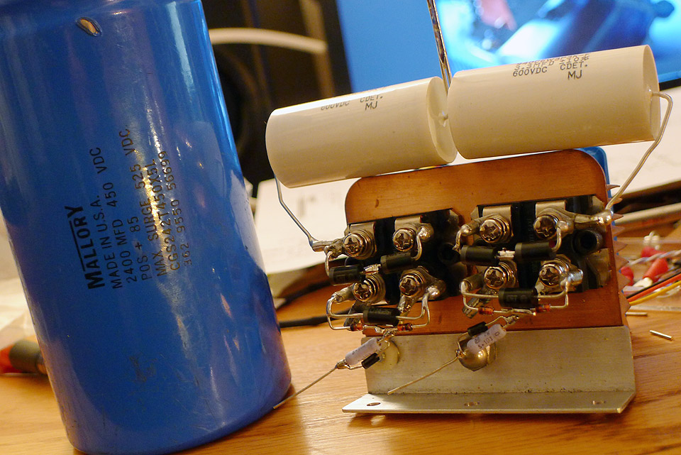
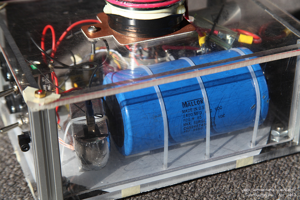
28 Sept 2011 Over the past few weeks, I have been gathering a list of components I plan to use, while trying to keep within my tight budget. I hope to make an order to digikey soon and get all the components at once. Most of the work has been in settling on a design for the coil. I had initially planned to use a half-bridge of IRFP-460 MOSFETs because I had some of them lying around. However, I eventually decided to work on the more robust 60n60 fairchild IGBTs. Today was a good day. In particular, I would like to thank MWS Wire Industries for kindly sponsoring 1600 feet of AWG30 Single PN-155 Green copper magnet wire for my project as a 'free sample'. Also, I cycled to the Metropolitan Pipe and Supply Company today in an attempt to find 2.5"-diameter SCH40 PVC. It seems that most hardware shops stock only 3" or 2". These are inconvenient because they have an other diameter of 3.5" and 2.5" respectively, while the 2.5" pipe has an OD of 2.875", as per my design specifications. The people there were very understanding and gave me a foot half length for no cost. With these two components, I have most of what I need to complete my secondary coil. 30 Sept 2011 The wire has arrived! Take a look at how beautiful it is. The quality of the wire has completely surpassed my expectations and I have to thank MWS Wire Industries. The next best I could find are on ebay. Fortunately, they are not particularly expensive. In addition, I have made an order on Digikey and hope it will arrive soon. Other people I want to thank include Bayley Wang who kindly donated a very nice full-copper heat-sink with a nice and powerful blue fan. This heat-sink will accept the two IGBT mini-bricks. The full-copper construction and powerful fan should provide equivalent cooling as a much larger static aluminium heat-sink. I also have managed to acquire a large Mallory 2500uF 450V capacitor (253J at full charge), 525V surge, as my bus capacitor. It is fairly large and places a lower-limit of my tesla-coil dimension.
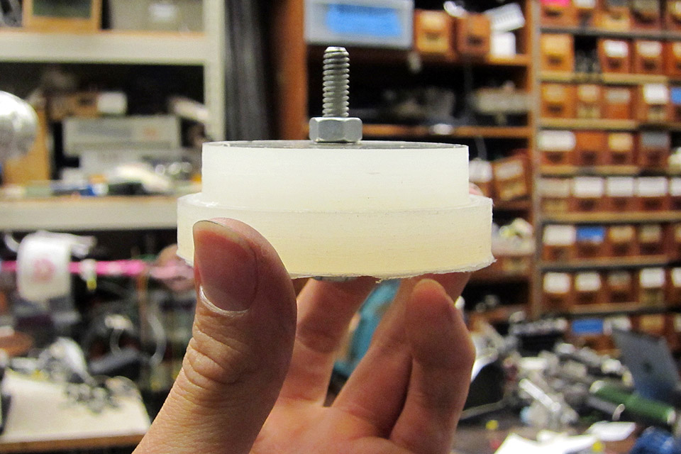
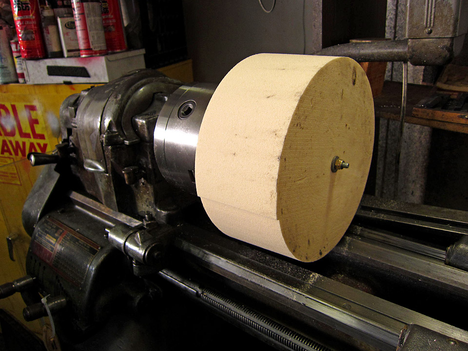
Looking forward to begin construction. Meanwhile, I can begin sketching up my PCB for the logic and drive circuit of my SSTC. 08 Oct 2011 The Secondary CoilWith the wire and pipe in hand, it was time to start making the secondary coil. I've wound several secondary coils already so this one should not be any more difficult. But before I can begin winding the coil, I'll first need to make the end caps. This will serve both as an aid for winding the coil (to keep the pipe centered on a rod), and also to serve as a mounting structure. I quickly machined two end caps using some junk plastic stock lying around (I'm not sure what material it is but it seems like UHDPE) on the lathe.
As you can see, part of the cap goes inside the pipe and is secured via three nylon screws. A hole directly through the centre will also accept another plastic bolt for mounting one end of the secondary coil to the enclosure and the other end to the topload. With this completed, I began winding the coil.
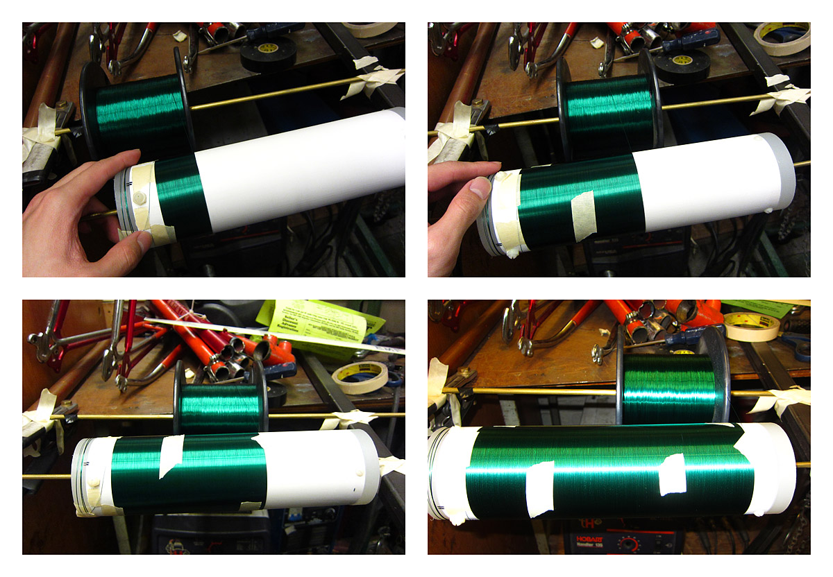
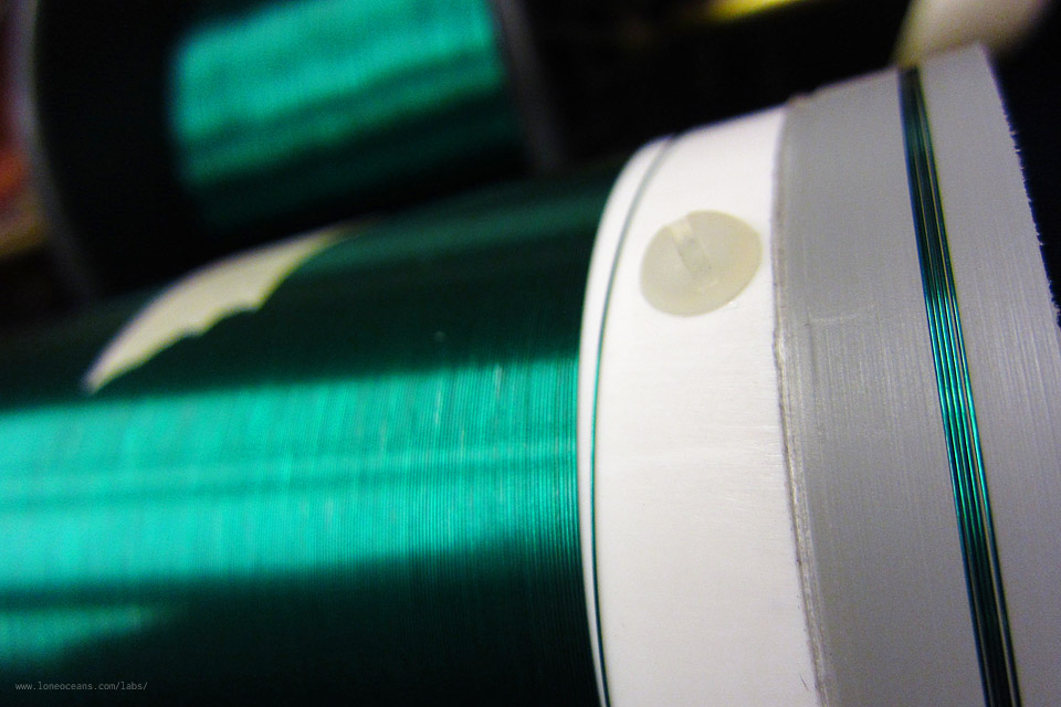
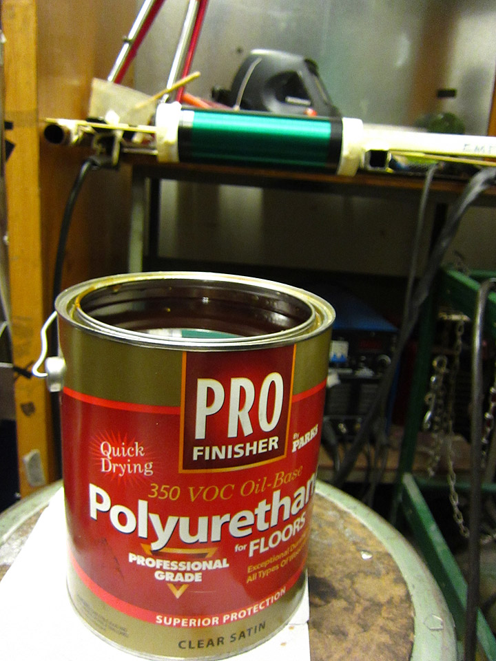
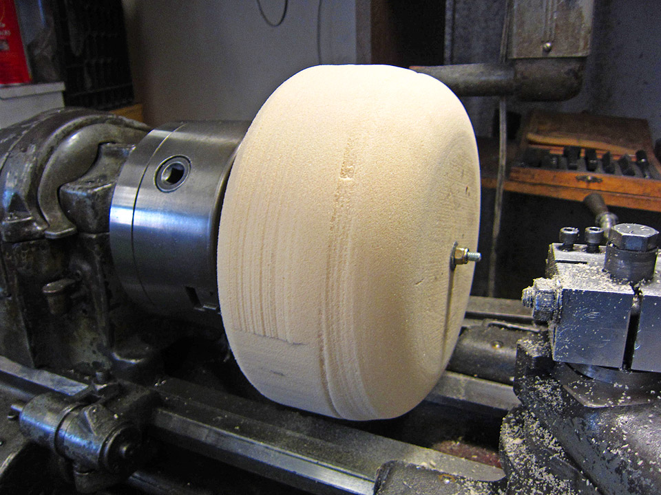
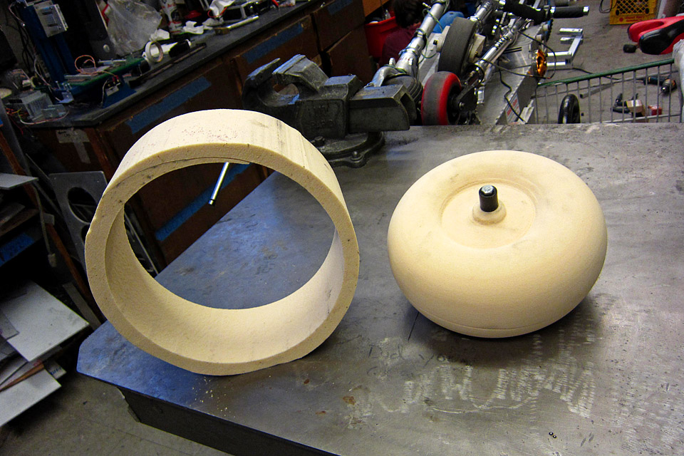
30AWG is not particularly thin, nor is my secondary coil very big (measuring 2.875" in diameter), so winding took just about an hour to complete. With about 8 inches of winding, that's just about 800 turns of wire. As you can see from the photographs, I taped the coil down at regular intervals as I wound it by hand. Once done, I secured the ends with one round of black electrical tape. To complete the coil, I varnished it with three layers of Polyurethane varnish. Any sort of polyurethane works well, but be sure to let each layer dry completely before applying the next layer. I found several thin coats to work very well in my Tesla Coils. The secondary coil is now complete! 11 Oct 2011 The ToroidThe topload of the Tesla Coil serves as a capacitor for the secondary part of the Tesla Coil circuit. It's traditionally always been the shape of a donut for several reasons - one of which because it produces a very nice electric field around the coil making it less likely to hit the base of the Tesla Coil, and also because it looks cool. There are several ways to make the topload, including blowing up a tyre inner-tube and pasting aluminium tape over, or for more fancy coils, using a spun or stamped metal toroid. Being unable to afford a nice metal toroid, I decided to make my own.
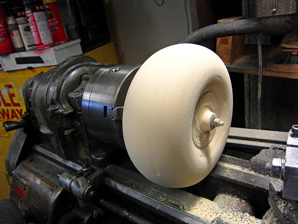
I found some nice modeling foam lying around the lab and decided to make my own foam donut. The foam was not thin enough so I glued two layers together using 3M-Spray Glue (Super 77), and cut a cylindrical block on the band-saw. I then mounted it on the lathe and spent the next half an hour carefully shaping the foam by hand using a rough metal file and sandpaper. This worked remarkably well. At this point, I should caution users that this method is potentially very dangerous so I do not recommend you trying it!
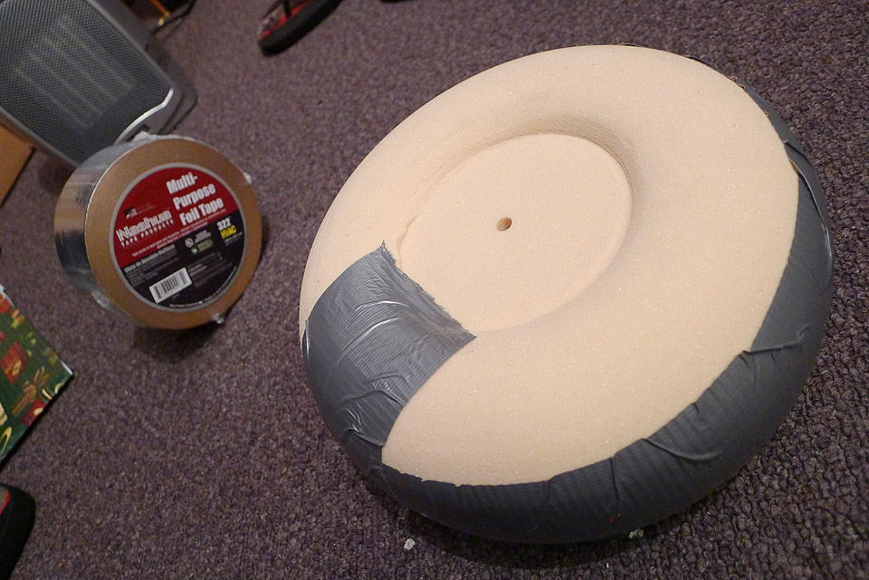
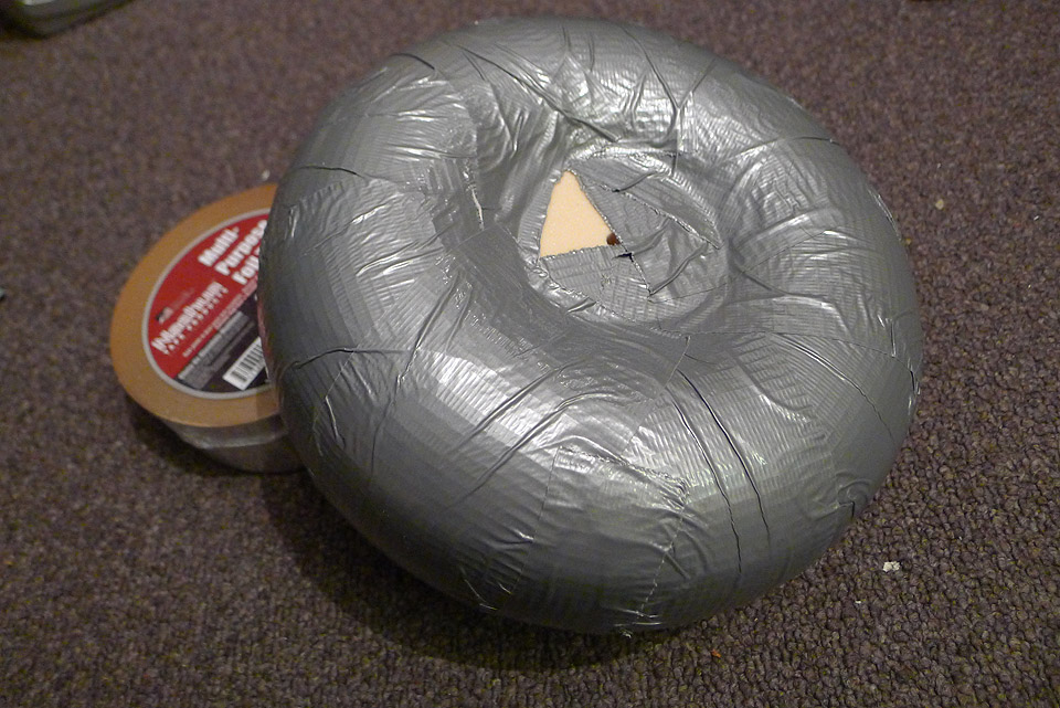
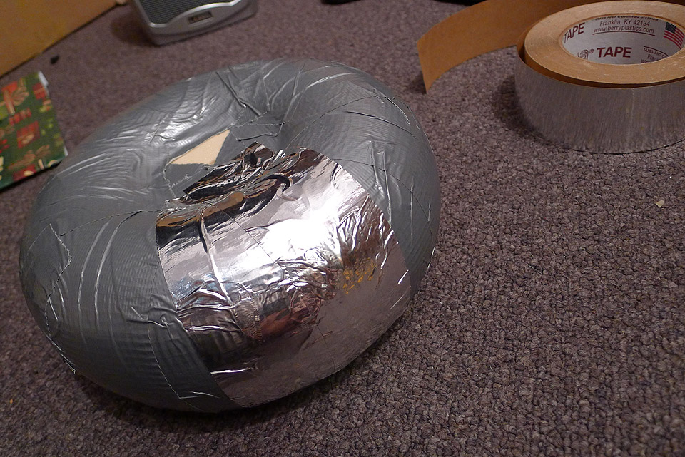
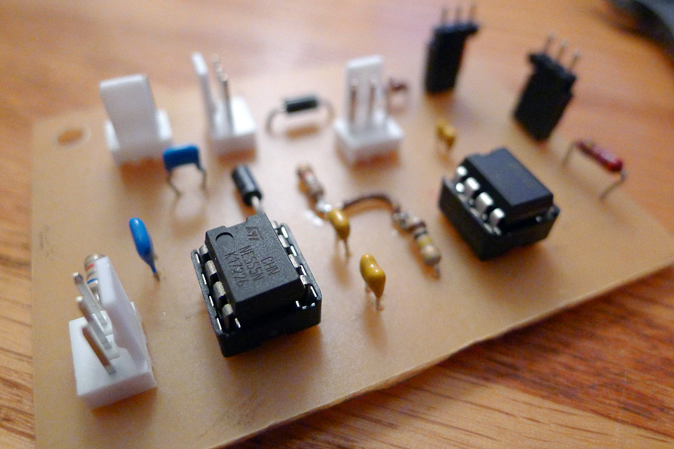
After a while, I finally got the shaped I desired. The final result is nice but not perfect because I shaped it entirely by hand, but it should work. Now the foam is rather fragile and easily dented. Therefore I wrapped it with strips of duct-tape, and then covered it with aluminium tape. The tape was then rubbed smooth using a curved object resulting in a reasonably smooth toroid. The topload is now complete! The topload measures about 3" (minor) by 8" (major diameter). 17 Dec 2011 The Optical InterrupterThe interrupter is an important part of a Solid State Tesla Coil of any type (including DRSSTCs). The reason for an interrupter is simple. When powering the Tesla Coil, one is sending huge currents at high frequencies into the Primary Coil via the power transistors. Unfortunately, these transistors are usually simply unable to handle these large currents (especially in DRSSTCs where the currents are in the order of several hundred amps) for any extended period of time without exploding. In many SSTCs (traditional design), it is possible to run them in Continuous mode, but this places a lot of stress on the components. The interrupter is a small circuit that basically interrupts the operation of the coil. Instead of running continuously, the interrupter acts as a sort of switch to turn the drive circuitry (to the power transistors) on for a short amount of time (say several hundred micro-seconds), before turning it off (for a few miliseconds) and then turning it back on again. This allows the duty cycle of the coil to be varied from 0 to 100%. In order to make my SSTC run more reliably, I built my interrupter using a simple dual-555 circuit. The goal of this circuit is to drive a Fiber-optic LED, with adjustable on-times, and adjustable intervals (frequency). This is easily done by using one 555 timer in Astable mode (which produces a continuous stream of rectangular pulses at some frequency), which feeds into another 555 run in Mono-stable mode, which at each triggering edge of the previous 555 signal, generates an output pulse of some duration (the on-time). The frequency of the Astable 555 and the on-time of the Monostable 555 are easily adjusted by varying the associated capacitor and resistor values (e.g. using a variable resistor). In order to make the interrupter circuit nice and compact, I decided to, for the first time(!), design and fabricate my own PCB. This turned out to be surprisingly simple to do and yielded very nice results.
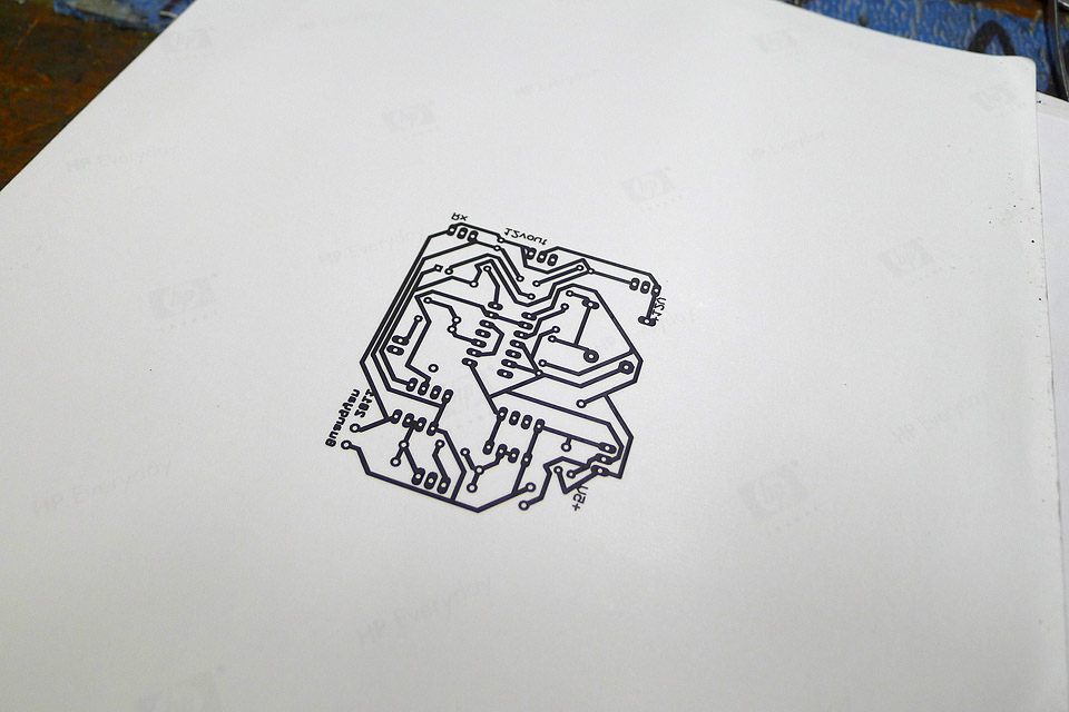
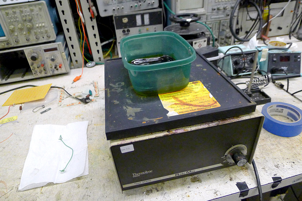
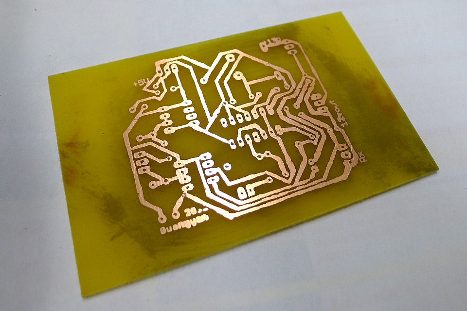
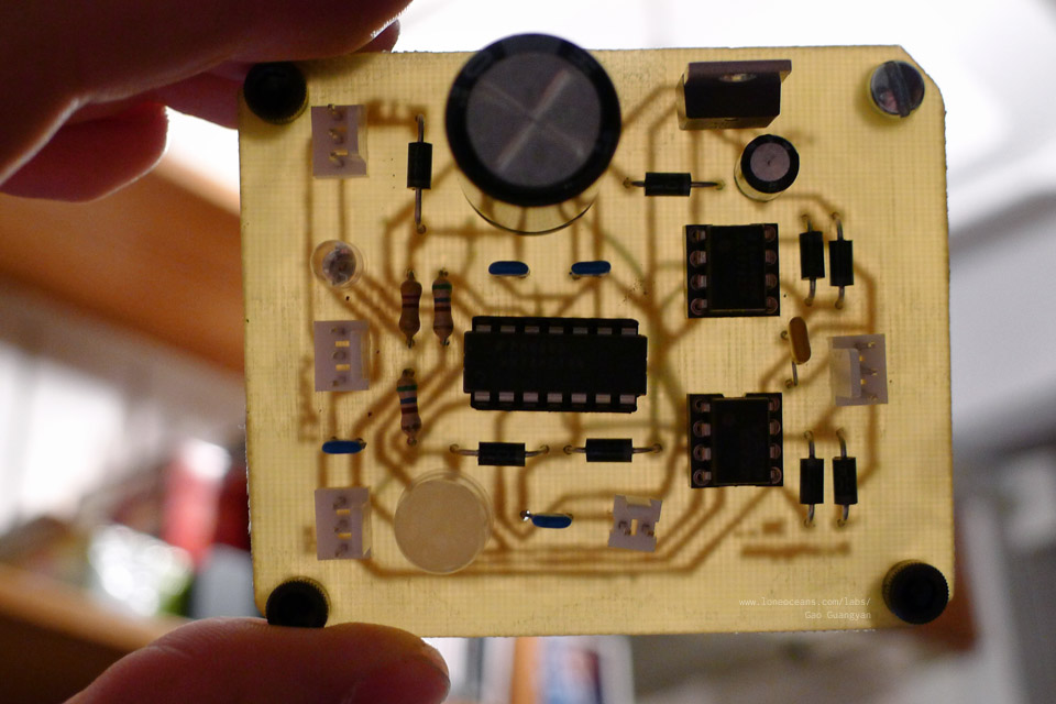
Here's how I made my own PCB. First, I designed the circuit in Eagle, which is perhaps the most commonly used PCB designing software in the world. This turned out to be very straightforward to use, and I was able to get my first circuit drawn up in an afternoon. Then I routed a single-sided PCB board, and printed out the traces using a laser printer onto magazine paper. It is important to use magazine paper - the kind which is somewhat glossy, very thin, and quickly turns soft when exposed to water. I then literally used a hot iron and ironed on the print (toner facing the copper side of a blank PCB board) onto the copper. The heat makes the printer toner re-bond onto the surface of the copper. In order to remove the paper, I then submerged the PCB into warm water and allowed it to soak until the paper was completely wet. Then it was simply a matter of scraping off the paper - the toner bonds surprisingly well to the surface of the copper. Finally ,the board is etched in a Ferric Chloride solution until all the copper is eaten away. The black toner is removed using Acetone.
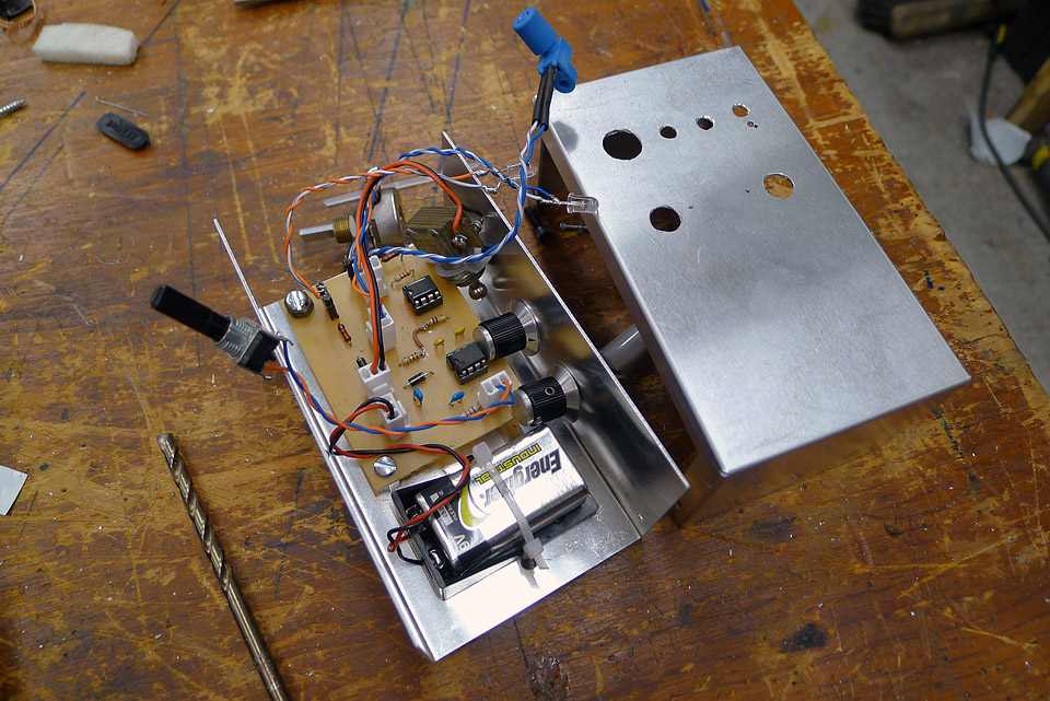
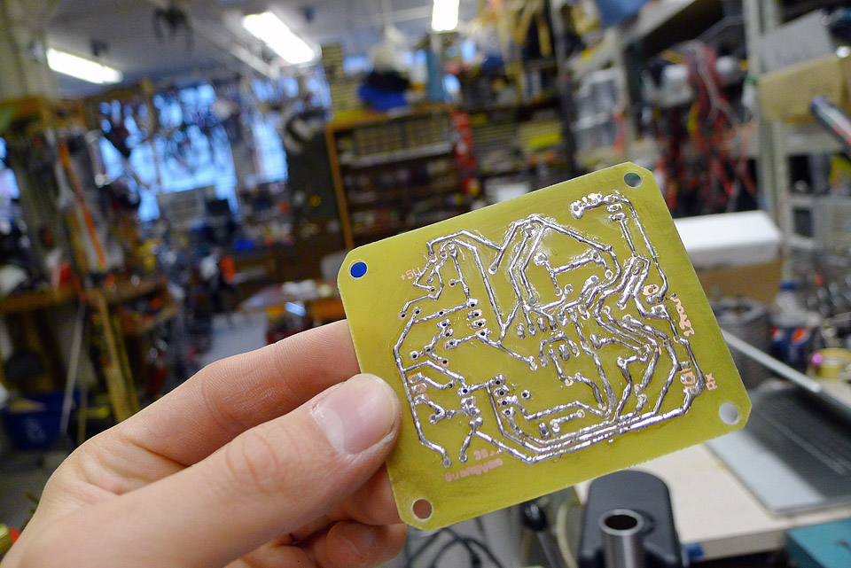
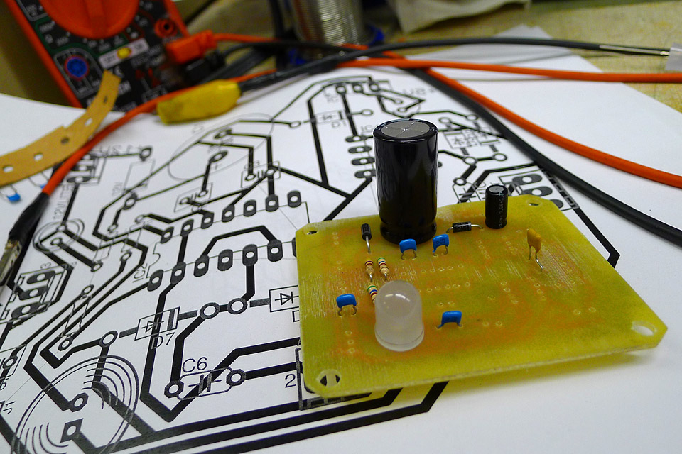
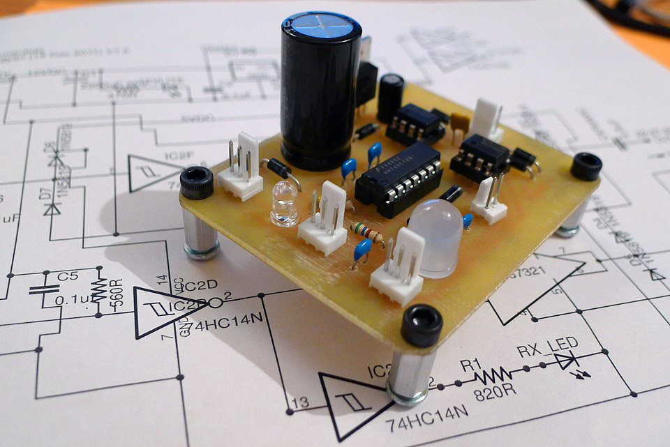
The result - a surprisingly nice home-made toner etching! It wasn't as clean as I had hoped for but I think it's not bad for a first attempt! I drilled holes carefully using a small drill press and a tiny carbide drill bit, and installed the components of the interrupter. Notice that I tinned all the tracks of the copper using solder to make it a bit more durable. Also note the use of 3-pin fan headers for connecting other components such as the 9V battery and the variable resistors. I tested the interrupter and it worked flawlessly! Success! The whole circuit board was then assembled inside a nice aluminium project box I bought from Radio-shack for $3. With the interrupter now complete, it was time to make the driver circuit which will interface with the interrupter via a plastic fiber-optic cable! This will allow me to control the operation of the coil safely at a distance with no risk of getting electrocuted since the fiber optic is entirely non-conductive. [ more technical information to come! ] 18 Dec 2011 60n60 Half BridgeThe most common circuit used in Solid State Tesla Coils for the main inverter for the primary coil is the Half Bridge - a variant of the classic H-Bridge. If you're unfamiliar with the terminology, the goal of the Half Bridge is basically to generate a voltage of +0.5Vs to -0.5Vs across our primary coil, where one end of the coil is held at 0.5Vs (between two capacitors in series), where Vs is the source voltage.
One end of the load (an inductor in this case representing the primary winding) is tied to a point between two capacitors to fix it at 0.5 Vcc. The other end is switched between the +ve Vcc rail and the ground. I decided to use a Half Bridge instead of a Full Bridge to save components and to maintain simplicity. [ more technical explanation to come regarding the bridges! ]
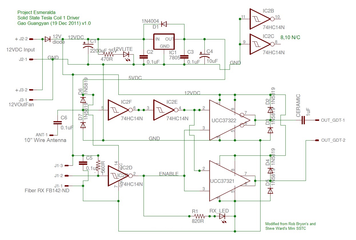
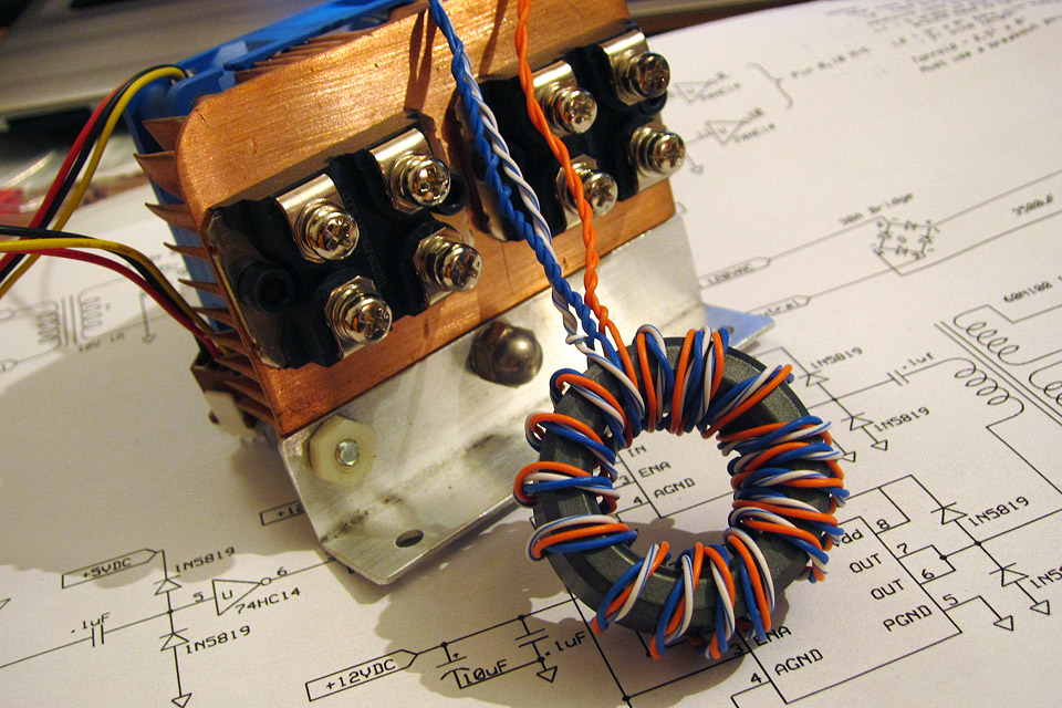
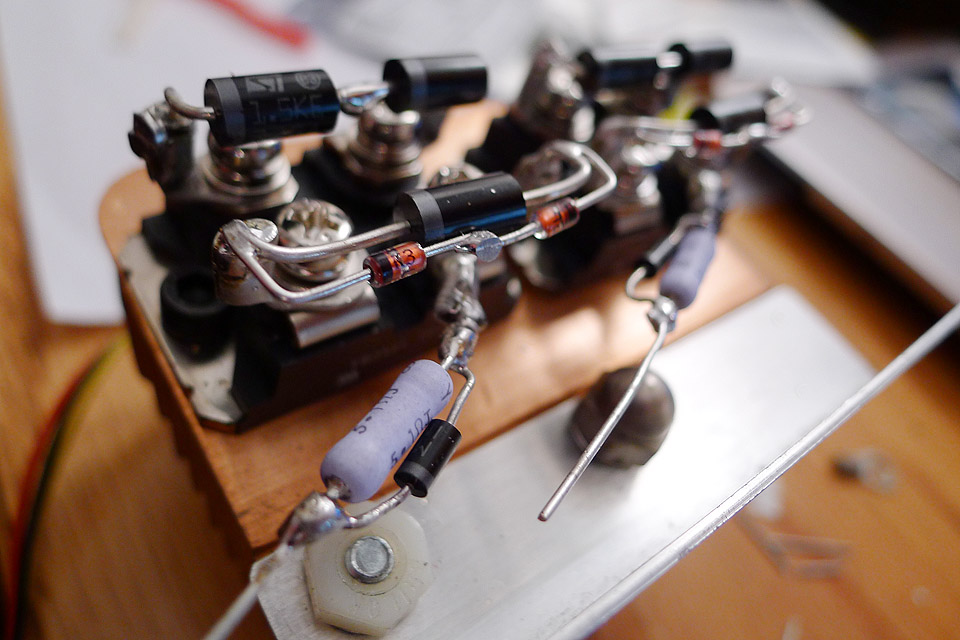
To keep the 60N60s nice and cool (and happy!), I mounted them onto a nice solid-copper heatsink. Notice the protection diodes, TVS diodes to protect the IGBTs from spikes. A 5.1 Ohm resistor was connected to the gates of the transistor. The gates of the bridge are driven via a Gate Drive Transformer, which is controlled via the Driver Board (see next section). 22 Dec 2011 SSTC 1's Driver and Control BoardThis is perhaps the most critical part of the operation of the SSTC - the driver, which drives the gates of the power transistors (in this case, the two 60N60 IGBTs). This design is very simple and is derived from Rob Bryon's SSTC which is based off Steve Ward's Micro SSTC. I modified the circuit slightly to suit my needs better.
Having had practice making my first PCB with the interrupter, I once again decided to design and fabricate my own SSTC Driver board. After a while in Eagle trying to fit everything together and routing the traces to fit on one-side, I was done! I found another type of paper which transferred toner better than magazine paper, and used it as my paper transfer sheet instead. This turned out beautifully. As you can see, the results are very nice.
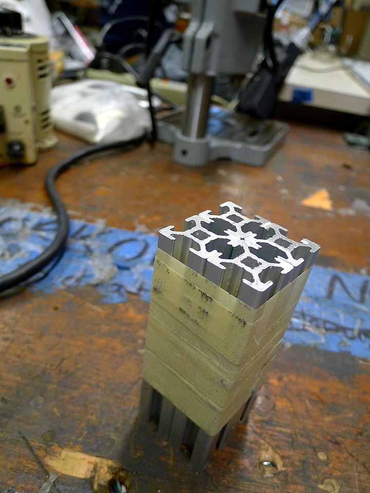
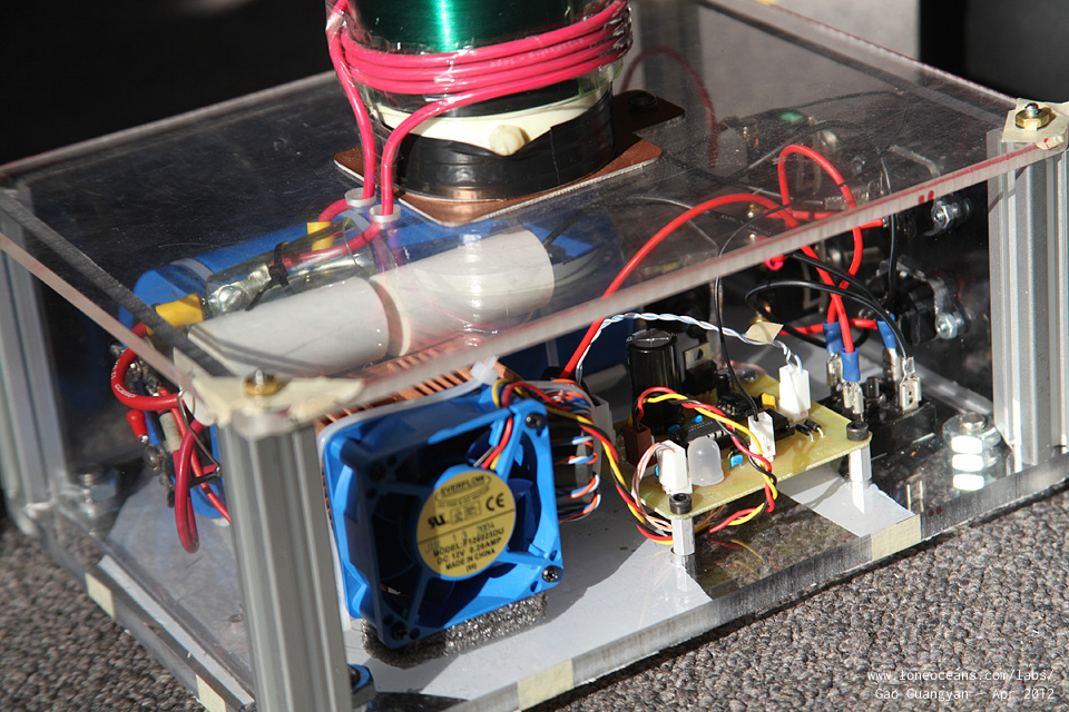
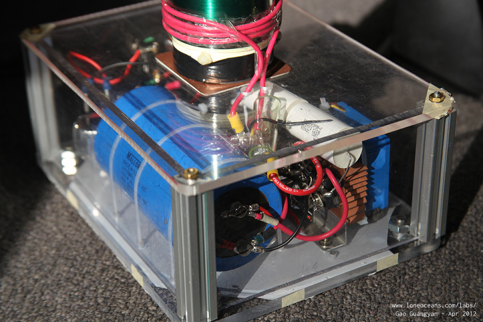
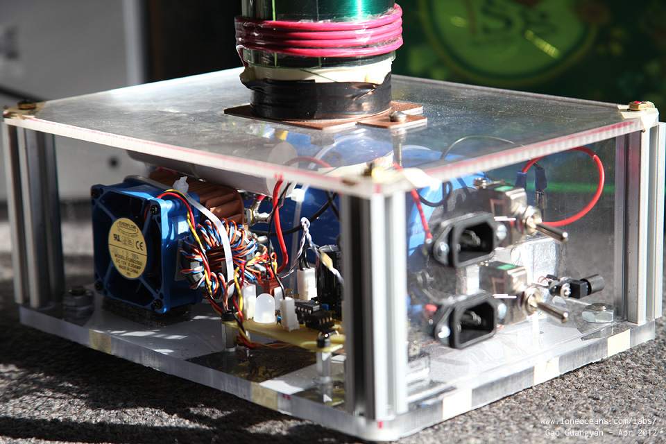
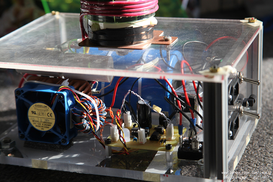
As per above, I tinned the traces for durability and made sure that there were no unwanted shorts or open-circuits, and carefully installed all the components referring to a large printout I made for reference. After a busy night, the driver is complete! The driver is a simple antenna-based feedback, which goes perfectly into resonance by detecting the E-field from the primary coil. The driver uses a pair of UCC337321/22 Mosfet Drivers (good for 9A) to drive a Gate Drive Transformer at + - 12V. This creates a 24V peak-to-peak square wave across a 18-turn 1-1-1 gate drive core. The two secondaries of the GDT are connected in opposite to each of the IGBTs, so that one is switched off when the other is on. It is very important to make sure they turn on and off in tandem otherwise a short is created across the primary capacitor, which will lead to an exploded half bridge! [ more technical information to come! ] Mar 2012 The Enclosure and Putting it all TogetherWith all the parts of the Tesla Coil complete, it's time to put it all together. I decided to make the coil durable enough to be transported back to Singapore, which meant it being tough enough to withstand being tossed around in a luggage bag. Therefore, I built the enclosure out of some nice Acrylic sheets I had lying around and four aluminium columns. The case is held together via four threaded rods.
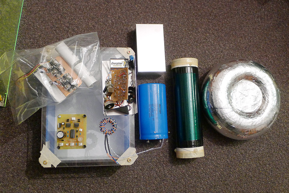
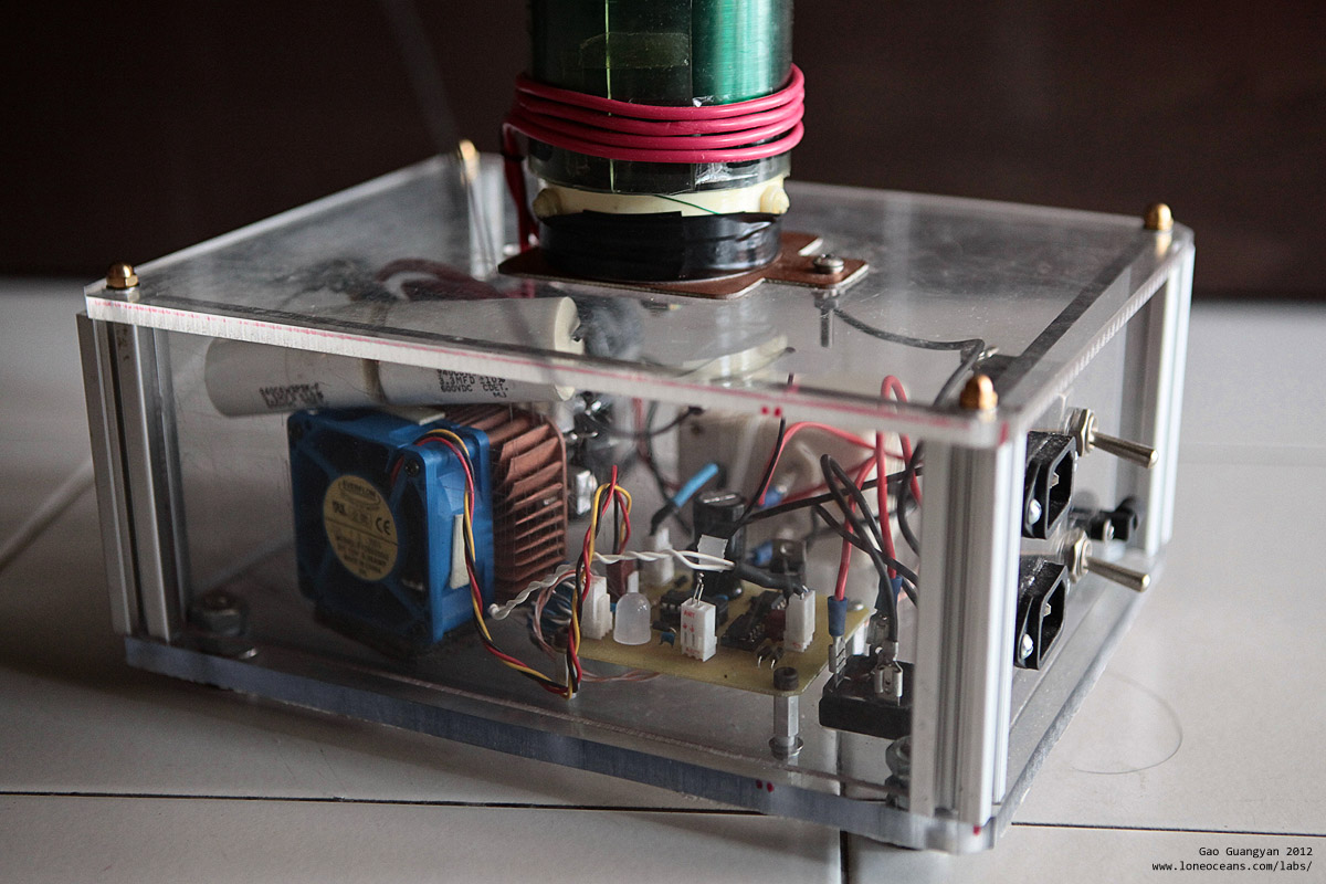
I also made the footprint of the tesla coil exactly the size of a sheet of Letter paper, so the footprint measures 8.5x11". This fits all the components comfortably!
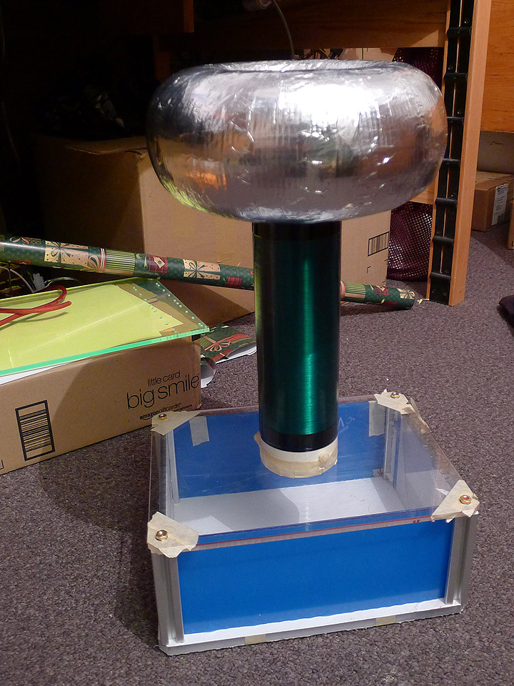
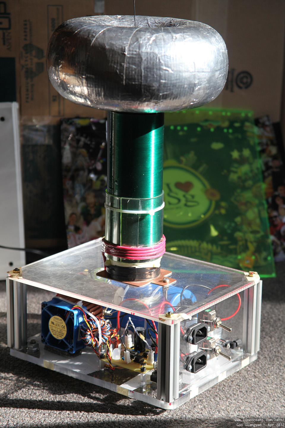
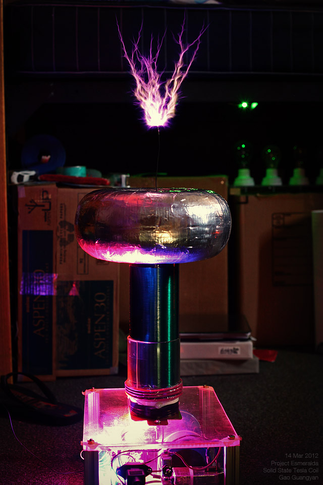
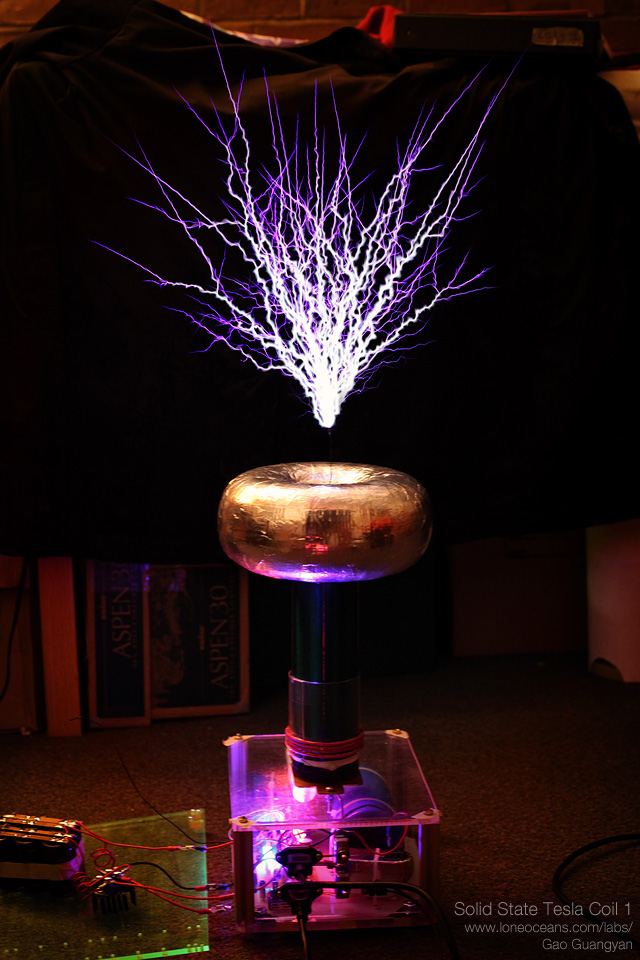
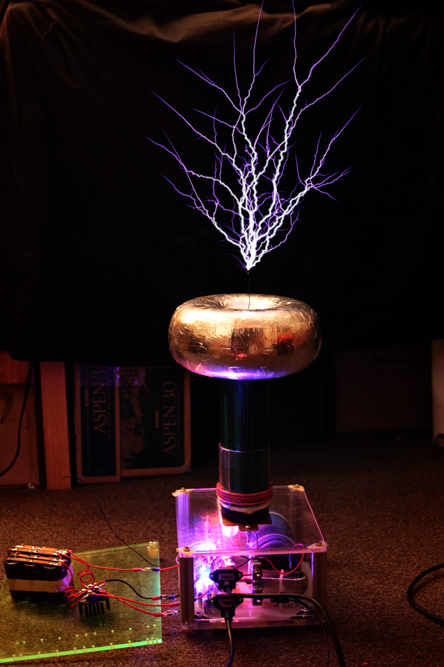
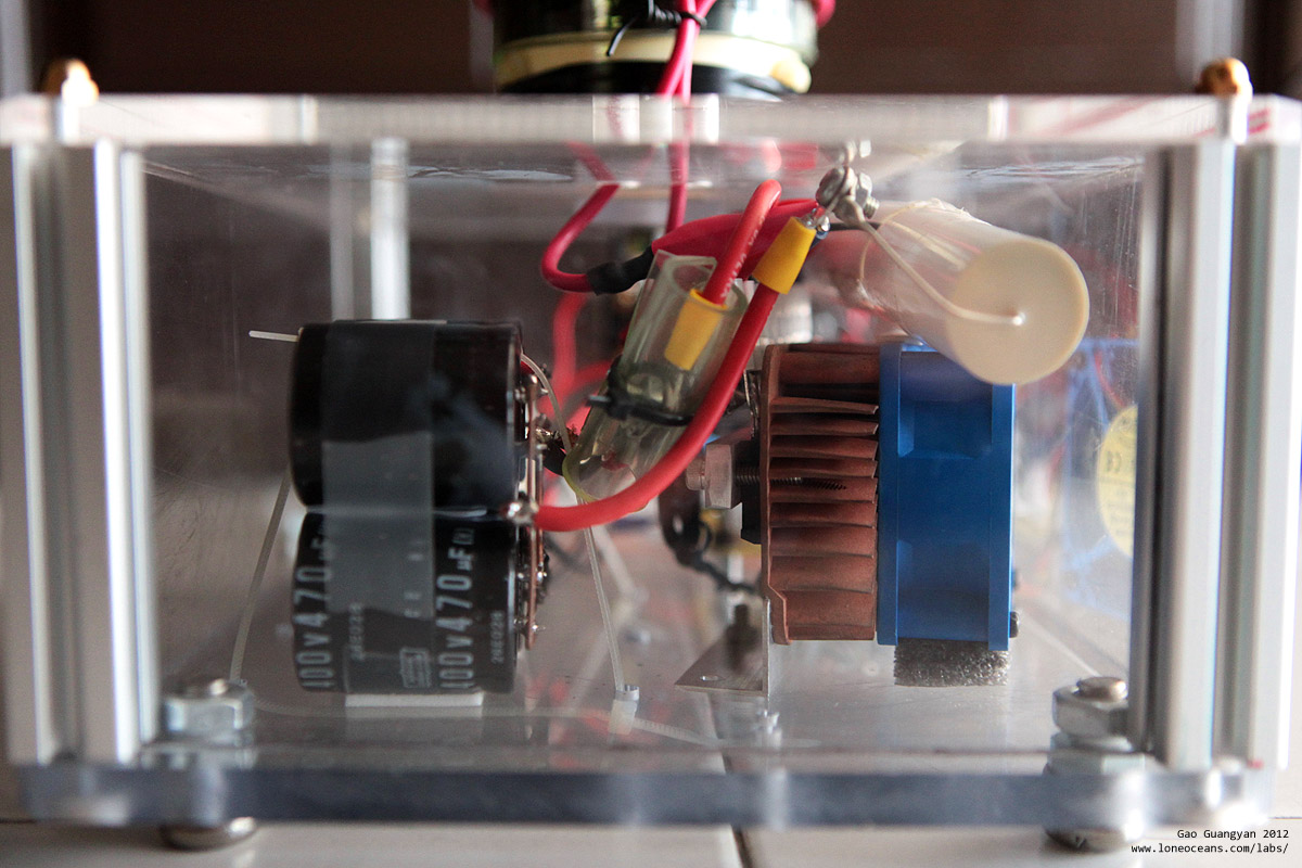
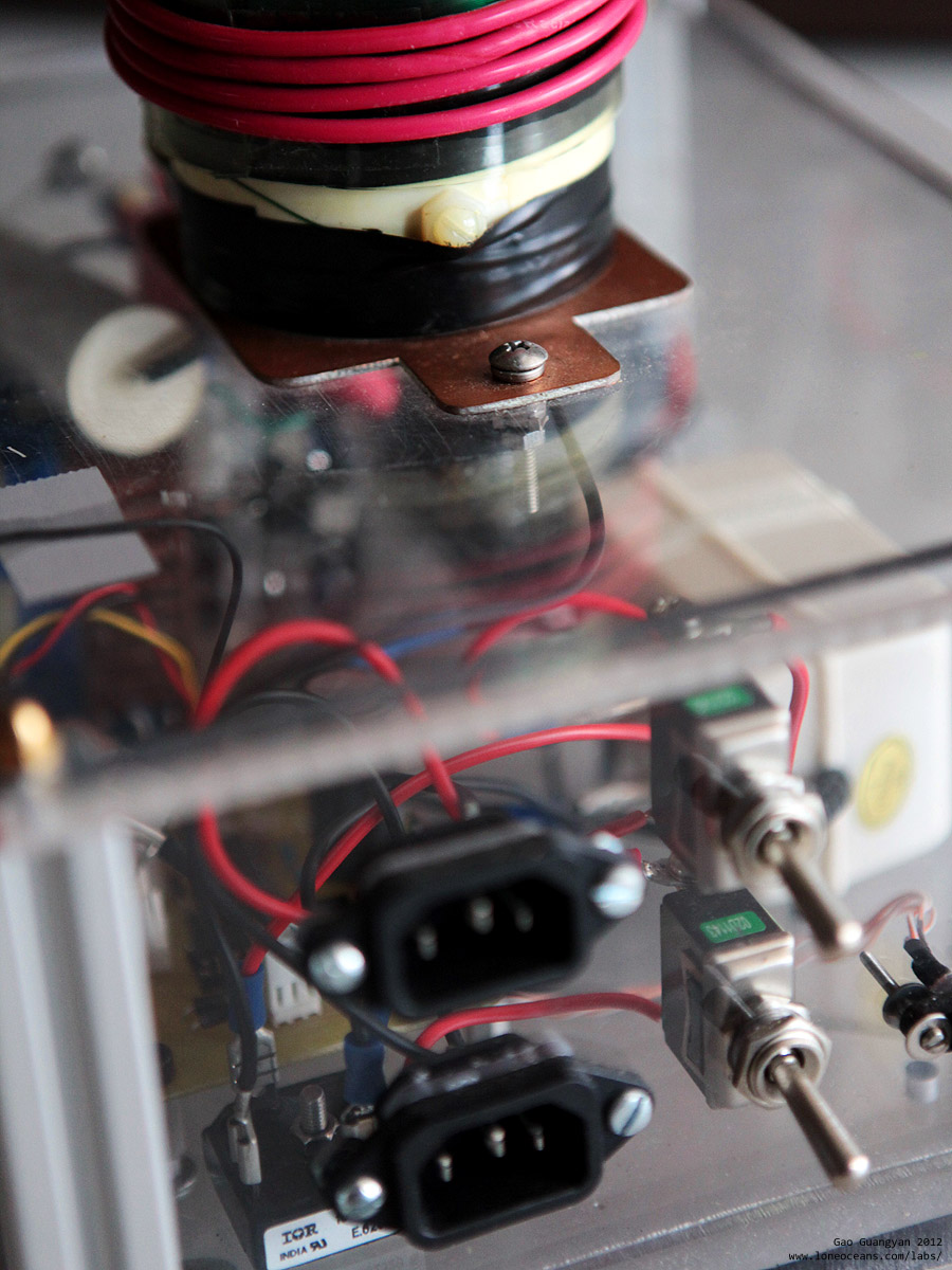
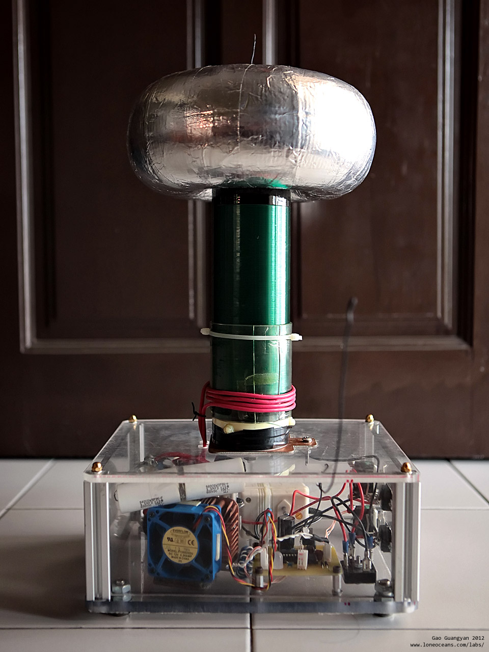
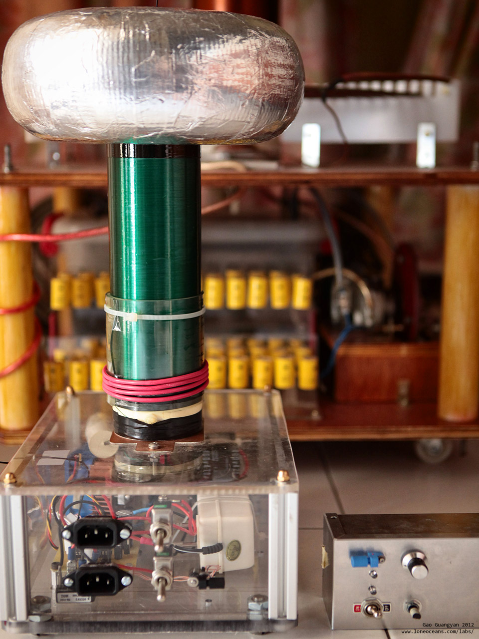
Above are photographs of the completed Tesla Coil. The primary coil comprises of 4 turns of multi-stranded AWG12 wire wrapped directly onto the secondary coil. A thick layer of soft PVC sheeting insulates the primary from the secondary. Also note the integrated 12V power supply the blue fan which cools the head-sink, and the large bridge rectifier which supplies directly to the large blue bus capacitor. The tesla coil accepts two IEC power cords -one for the 12V power supply and the other for the bus, as well as two switches, and a fiber optic receiver which connects to the driver.
With this, my first Solid State Tesla Coils is now complete! But will it work? Stay tuned to find out!
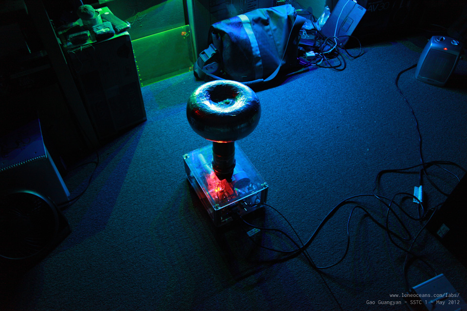
Project Esmerala - SSTC 1 is now complete!Results - Photographs and Videos13 Mar 2012 First light! After several months in the making, it's time to see if the coil will work or not! I plugged the coil into a variac and slow turned up the voltage to about 40V, which the coil should begin producing some visible sparks. I set the interrupter to the lowest frequency and turned up the pulse-width to about 200us - and sparks appeared! I realized that my interrupter was not configured well with a normal SSTC operation, which will do better with a pulse width of a few mili-seconds instead of micro-seconds, so it's time to adjust the interrupter. This is easily done by changing the capacitor of the Monostable 555.
Above shows the coil working at about 200us on-time per spark at about 170VDC on the bus. SSTC 1 is alive! 14 Mar 2012 It's Pi Day today! It could not be a better day to test SSTC 1. My original interrupter was set with a duty cycle that was too small, which isn't the best configuration for a normal SSTC. I didn't have any capacitors at hand to change the 555 interrupter circuit. However, since the SSTC is optically triggered, I found that flashing a light through the fiber-optic yielded excellent results.
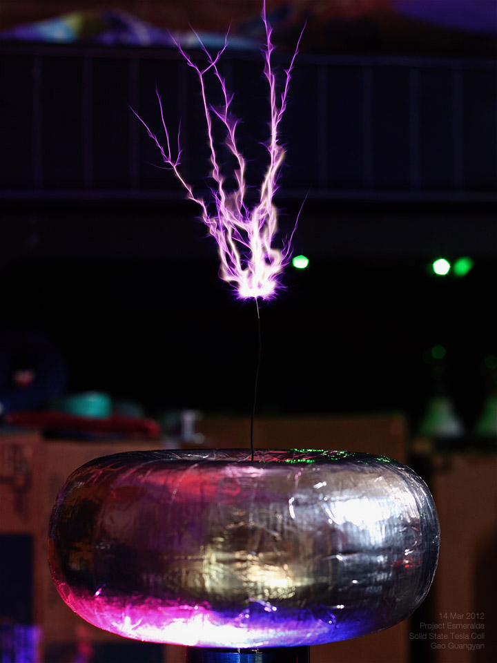
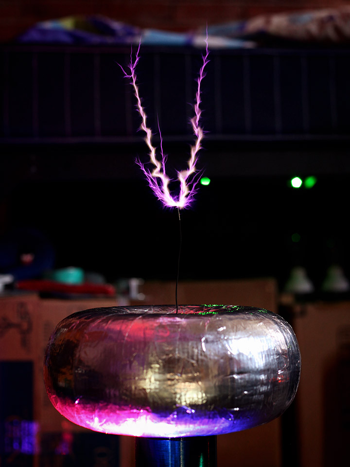
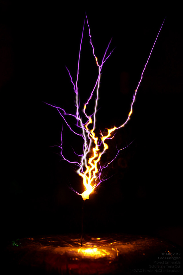
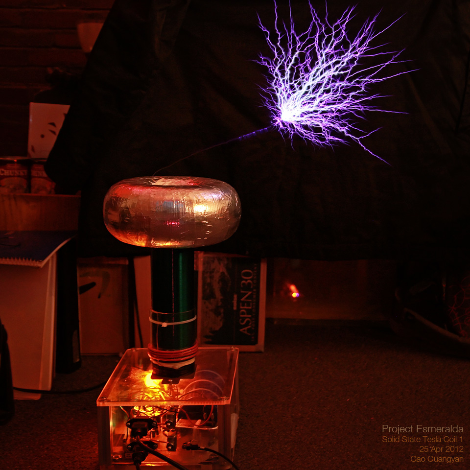
Note that this cannot be done with a DRSSTC - only for SSTCs which are capable of continuous operation (usually referred to as CW or continuous wave). The above photo show the coil in action at 120VAC input. Note the very hot, fat sparks with a very curious spiral / corkscrew formation. It's a fascinating shape! 16 Mar 2012 I modified the interrupter to achieve good performance with SSTC 1, by adjusting the circuit to allow for pulse widths around 1.5ms.
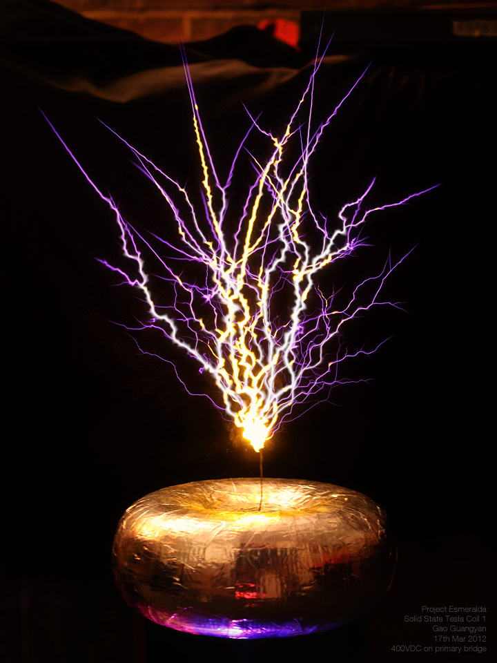
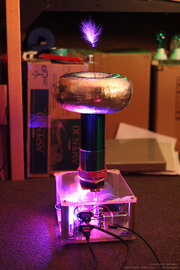
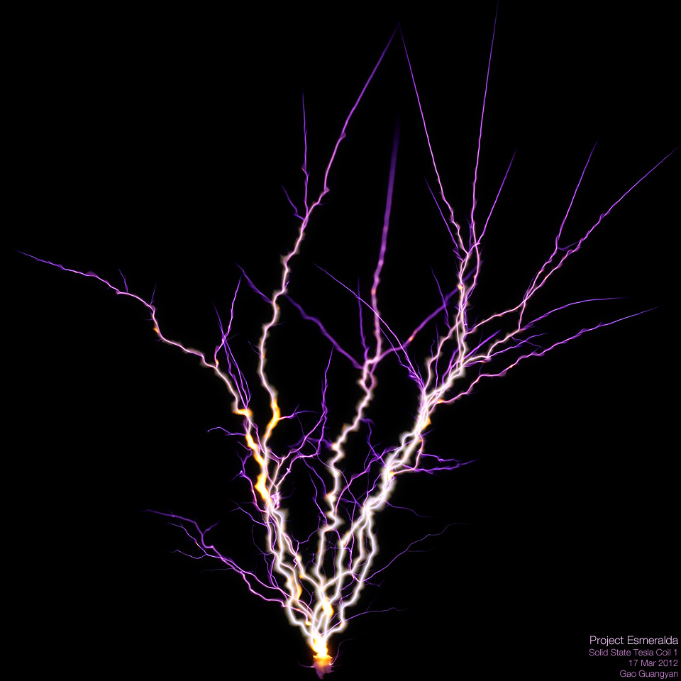
Above shows the coil running at 120VAC input with the longer pulse widths. This allows sufficient time for power to be transferred from the primary to secondary circuit. A bit of salt was added to the breakout point which lends a yellow colouration to the sparks as the sodium ionizes and glows. I'm currently working on a voltage doubler to bring almost 400VDC to the bus - what the coil was originally designed to handle! 17 Mar 2012 I then constructed a simple Voltage Doubler, which takes in 120VAC line voltage, rectifies it and doubles it up to 339VDC peak. This is then fed directly to the Tesla Coil primary bus. My variac is able to boost 120VAC to about 140VAC, so at full power, the coil sees roughly 395VDC peak, almost 400V! This is still within spec for all components. I plugged in all in an turned on the interrupter...
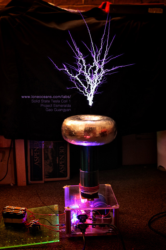
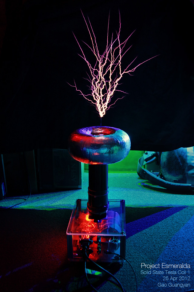
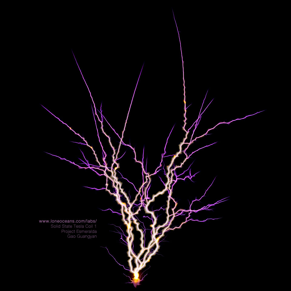
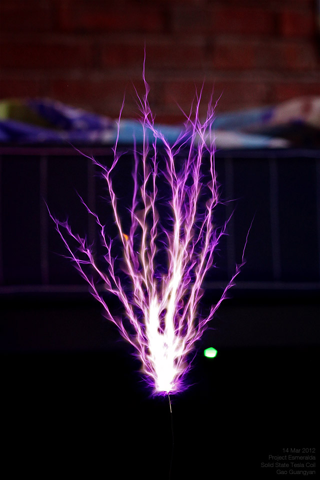
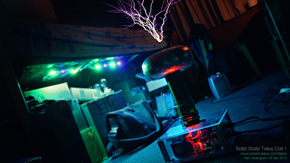
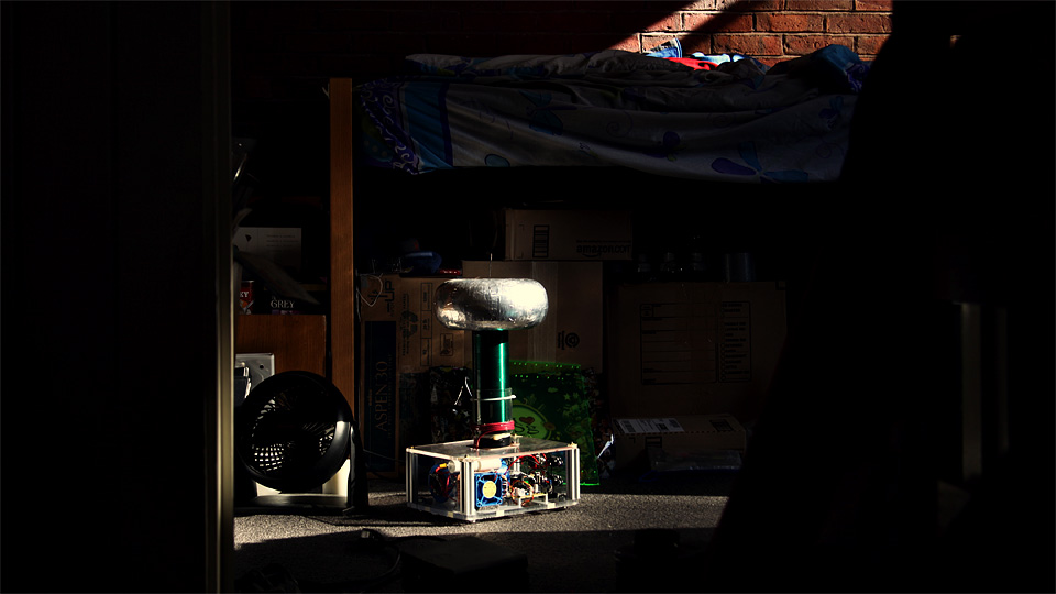
The results are spectacular, and more than I could ask for. The coil performed admirably and reliably. I achieved about a maximum of 19" spark to air (about 48cm), which I am very pleased with considering the 8" secondary coil length. This is almost 2.5x secondary length to spark length performance! A bit of salt can be added at the tip of the breakout point (see 3rd image above) which gives a mesmerizing yellow colouration to parts of the sparks. Very cool. Above is a video showing the coil in action! Notice how the duty cycle and beats per second can be adjusted via the interrupter. The voltage doubler box sits exposed outside and I do not recommend this being done. I plan to put the doubler inside a grounded metal case very soon. 25 Apr 2012 I installed new blue and green LEDs under my bed (they are of course wired up to dance with music - see my LED lighting project here!), and thought it would make a fancy background for the coil. I also made a few small changes to the coil, such as changing the LEDs at the bottom to a less bright orange one (so it doesn't saturate photographs). I also enclosed the voltage doubler in a separate box so everything is less of a safety hazard now!
I also tried changing the breakout point by adding a very long wire. Mysteriously, the spark length shortened significantly, but the results are good nonetheless! Very happy with how my coil is running. 12 May 2012 My good friend Jonathan came to visit today!
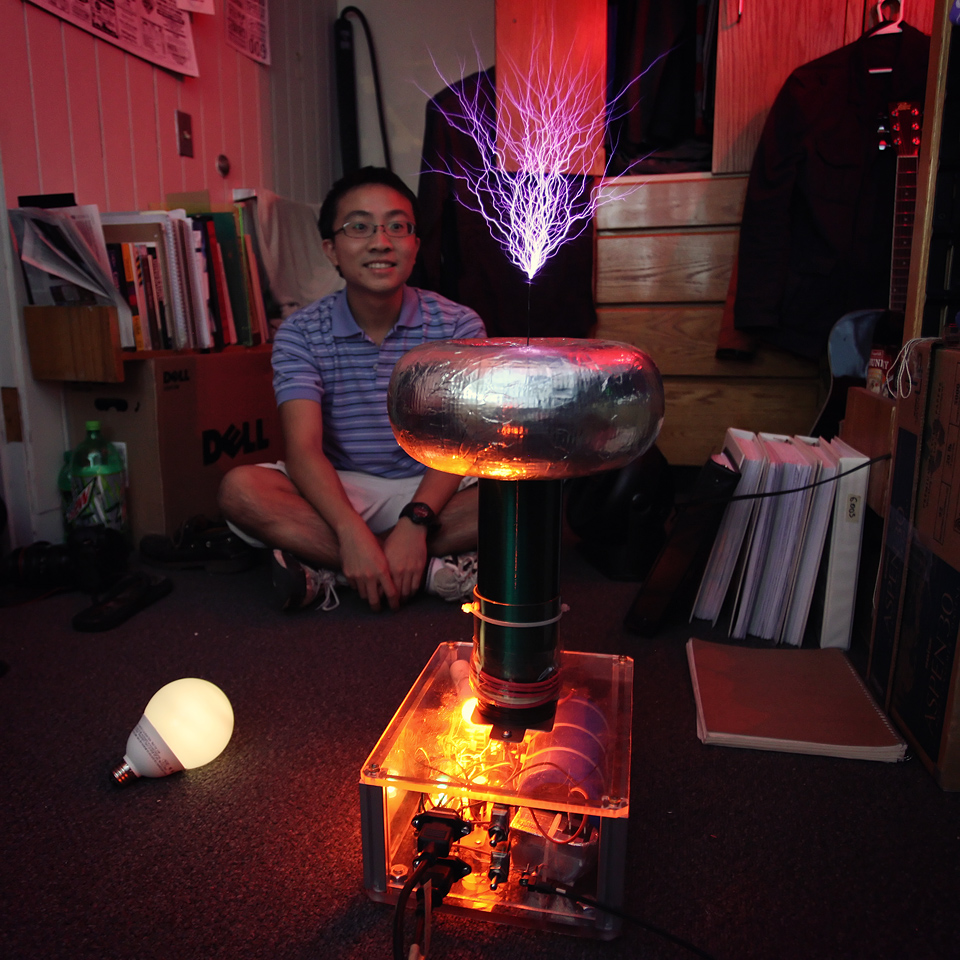
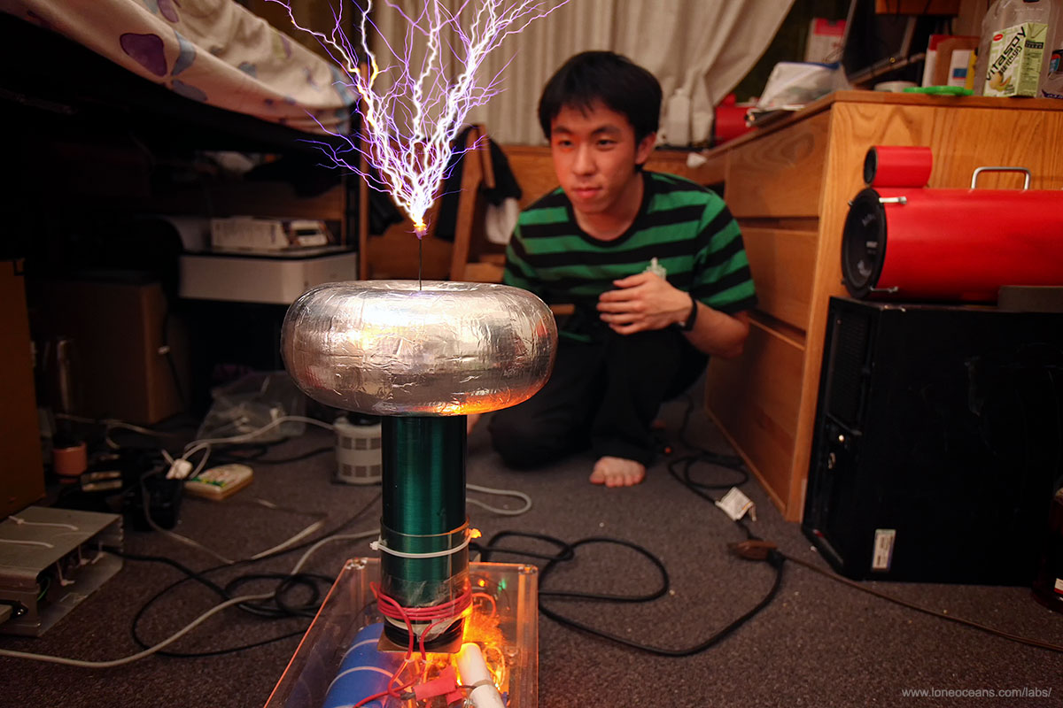
We fired up the Tesla Coil and it performed admirably. Here's a photograph (left) of Joanathan and the coil running at 120VAC and lighting up a fluorescent bulb wirelessly, just as Nikola Tesla had intended it to be! :) The photo on the right is me operating the coil from Jonathan's point of view! June 2012
The photograph above shows the coil in my room in school before it was packed up and shipped to Singapore. A few changes will be required (e.g. changing the 12V Power Supply to one that runs on 240VAC) before the coil is operational again. August 2012 *Update!* Solid State Tesla Coil 1 has been brought back to Singapore and now lives here permanently with 240VAC without a pesky voltage doubler box!
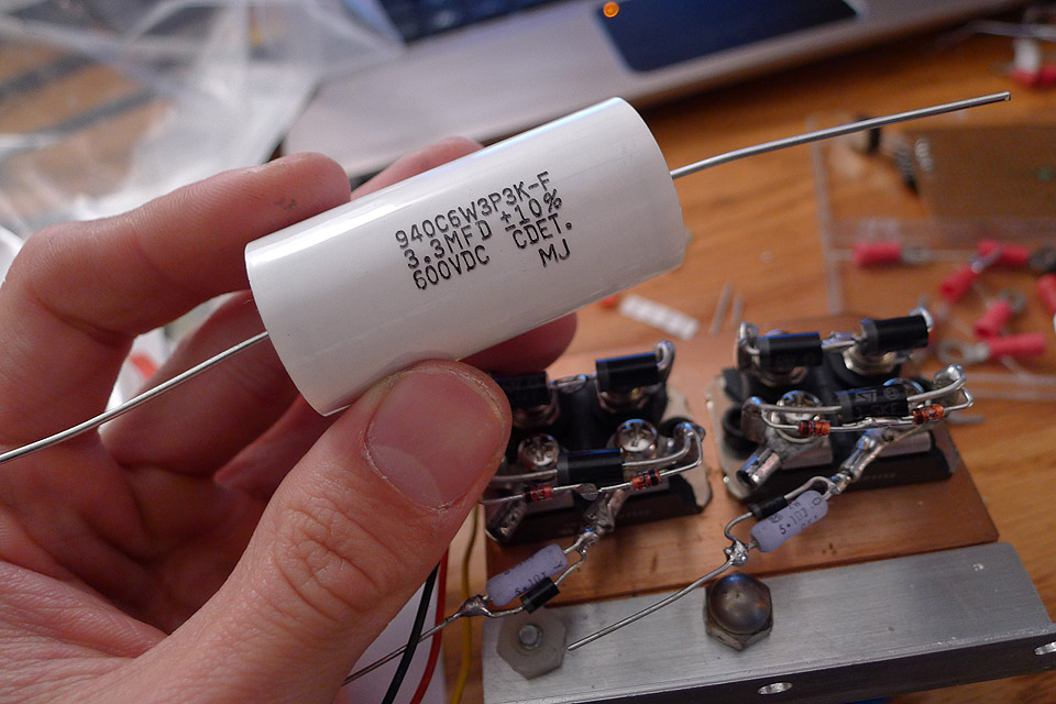
The coil has received some small adjustments since, and now runs on a halfbridge of IXGH 60N60C2ND 75A 600V IGBTs in TO247-like package, and I've also replaced the capacitor with a more reasonable and smaller array of four Nippon Chemicon 400V 470uF capacitors in series. It now runs directly off 240VAC mains for about 380VDC on the bus with the same excellent performance as before. The 12V power supply has been replaced with a small iron-transformer power supply.
The above photographs show the details of SSTC1 and compared to the newly improved Tesla Coil 2. It's now time to progress to DRSSTCs! Some updated specifications After taking into account insulation thickness of the windings, I should have closer to 730 turns of wire on the 8" winding length. With a 2.875" diameter secondary and a toroid measuring 3 x 8", this puts the secondary resonant frequency around 465kHz or so. This high frequency is not ideal for the IGBTs and in hindsight, I should have made a lower-frequency setup. However, the high frequency probably contributed to the sword-like sparks of the coil, and the big toroid helped in increasing the brightness and power of the sparks. Good LinksHere are some nice and very useful web pages. [More to come soon!] Back to main page
Loneoceans Laboratories. Copyright (c) 2003 - 2025 Gao Guangyan, All
Rights Reserved. Design 3. |
Removal of any material from this site without permission is strictly prohibited and will result in infringement of copyright laws. Disclaimer: Projects and experiments listed here are dangerous and should not be attempted. www.loneoceans.com/labs/ ... page generated in 0.00015 seconds |