Over the past two years or so, I successfully built a working QCW Tesla
Coil (see
QCW 1.0 and 1.5). After a lot of work,
experimentation and rebuilds, the eventual coil performed
very well and I was very impressed by how large I could make the sparks
relative to the size of the coil via the QCW topology. This made me
realize that the QCW is a fantastic candidate for a small table-top coil
capable of producing fairly impressive sparks. This motivated me to
build a QCW coil as small as I can, with the goal of developing an
ultra-portable tiny QCW coil.
My QCW 1 employed a buck-converter front end with a max primary current
of around 160A. For this new coil, the goal is to create a smaller coil with
a peak current closer to 60A, and driven by a completely differently
drive technique known as Phase-Shifted modulation, essentially eliminating
the bulky buck-converter front end though at the cost of increased drive
complexity and hard switching. Drive is implemented via a newly
developed driver with a micro + CPLD-like implementation. The result should be a significantly
smaller coil capable of being run on a small table and easily
transportable in a small bag / box.
[This page is still under construction!]
For more information about basic QCW operation, please see my previous
QCW pages :). Project Status - Project
Completed with >2' sparks.
Thanks for
visiting my page! If you have any questions, wish to share your
projects, or feel that my projects have inspired you in one way or
another, feel free to email me at loneoceans[at]gmail(dot)com. I'd love
to hear about your projects too. :-)
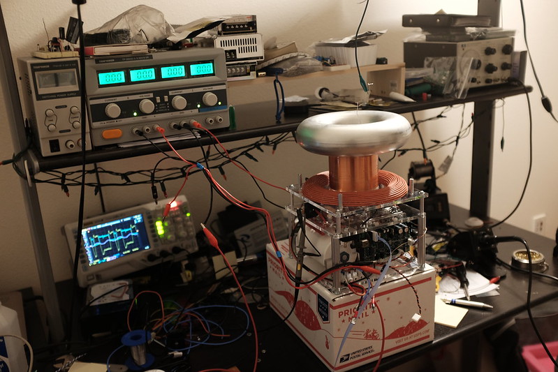
Specifications (Oct 2015)
- FGA60N65SMD Full Bridge Inverter '80mm Bridge',
15R gate-resistor
- 5.875nF MKP 3.2kVAC/8kVDC MMC
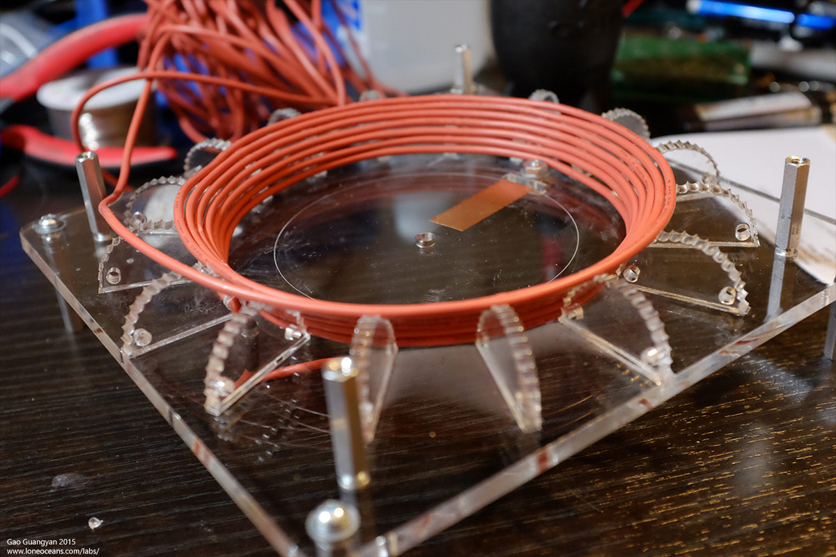
- 17 turn 1.2" dia 18AWG "half-donut" primary coil
- 60Apk Max Primary Current
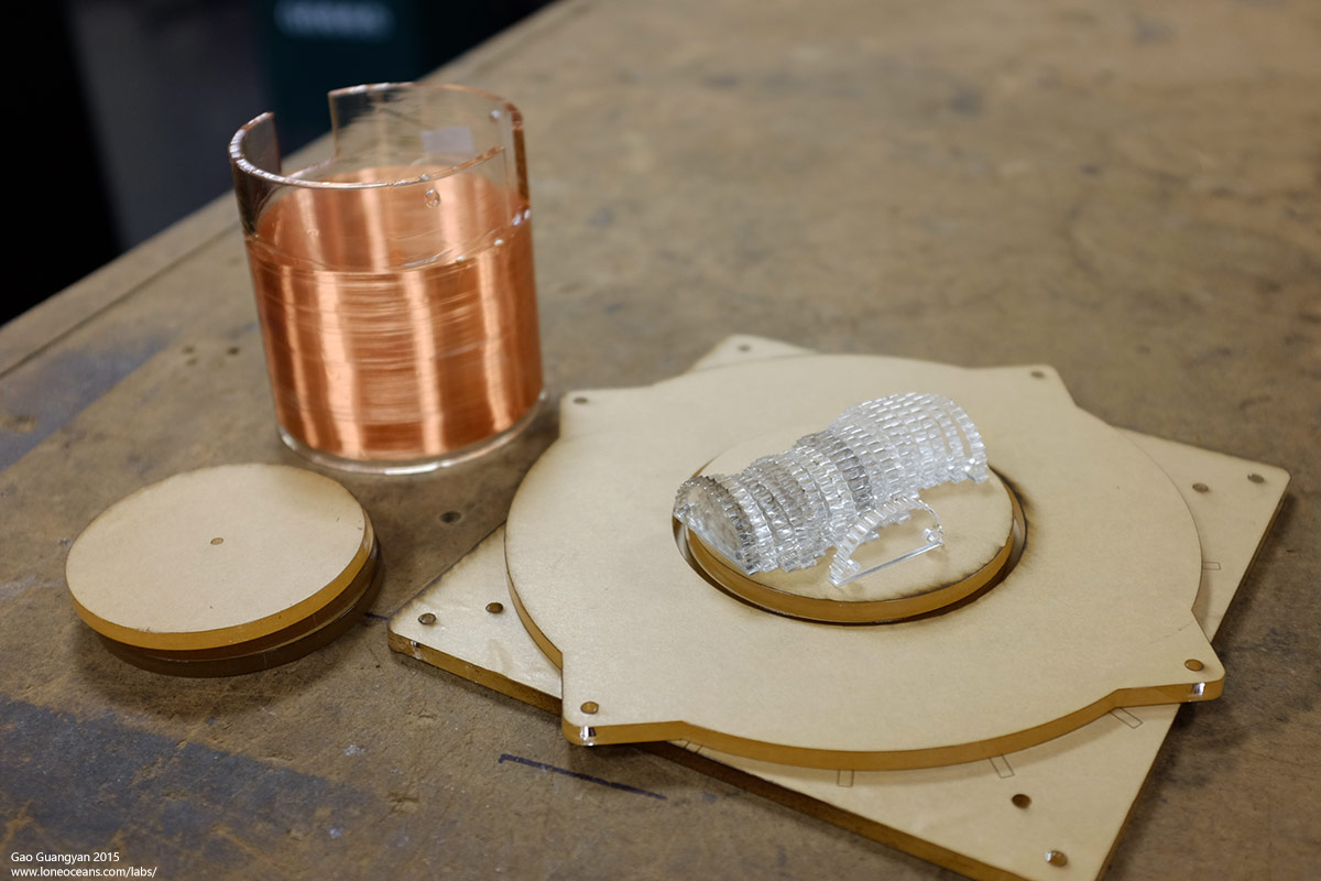
- Secondary coil 2.41" x 3.52" 38.5AWG x ~610 Secondary
- 8 x 2.09" Spun Toroid
- ~308 kHz unloaded secondary frequency
- Run from 90-260VAC input
Size Goal (Oct 2015): Fit inside a USPS Medium-sized box
Performance Goal (Oct 2015): 10x secondary length = 2 feet
For much more videos and images of the coil in action,
please scroll down.
Sept 2015
Design and Construction
The newest frontier of Tesla Coils in the modern age is
the QCW DRSSTC capable of generating long, fat sparks with clever drive
techniques. If you are not familiar with QCW operation, please read my
QCW 1 and QCW 1.5 pages to
learn about basic QCW principles otherwise the following may not make
too much sense.
Overall Project Goals
In this project, I came up with a few concrete goals I
could work towards. Having a clearly defined set of goals will help
serve as constraints and aid in any engineering decisions and design I
have to make along the way.
Project Goals
- Produce sparks >10x the secondary coil length
- Demonstrate reliable operation
- Planned running BPS of 0.5Hz to 5Hz
- Operate at ~300V ramp with 240VAC input
- Implement a new phase-shift drive technique
- Be compact enough to fit inside a medium-sized post box
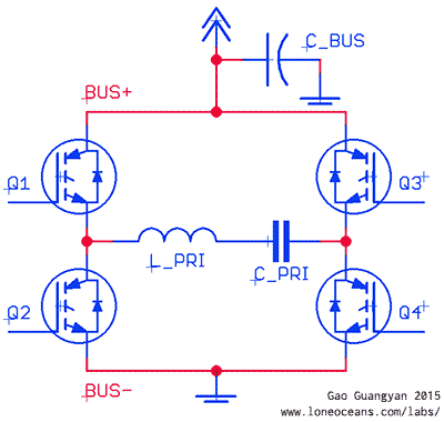
Improved Drive Techniques
Phase Shift Drive Technique
Phase shift control is a method where a 50% duty cycle
is maintained on each half bridge, but the relative phase of one pair is
shifted relative to the other. By adjusting the phase angle, one can
easily control the effective duty cycle. This eliminates the bus
modulator front end.
In a bus-modulated QCW, C_BUS is replaced
with a high current buck converter or similar modulated supply. This
allows resonant switching operation as V_BUS increases in a ramp, which
each half of the bridge is switched pi out of phase. In phase shifted
drive, the idea is to eliminate the bus modulator, but doing some trick
to mimic the resultant behavior. To achieve this, we allow one half of
the bridge (Q1 Q2 or Q3 Q4) to switch normally in resonant switching,
but shift the phase of the other bridge relative to the first half. Lets
take a look more closely how this works.
Above shows the relative phase of the bridges along with
the primary current. In normal switching operation, the green and red
show the switching action of each half bridge (remember that the two
switches in each half must be out of phase always, so we simplify it
here by just showing say the top switches). The orange and yellow
traces show switching of the 2nd half of the bridge as the phase changes
from 180 to 0. At 0-deg shift, there is always 0 potential difference
across the primary, whereas at 180 deg, there is always the bus voltage
across the primary.
By ramping the shift from a low number to 180, the
result is a variable duty cycle. Because of this, note that half the
bridge is always switched in resonance and half doing hard switching
with the hardest switching at 90 degrees. In order to share the load of half switching, the driver
goes one step further toalternate hard switching between the
two halves every cycle.
[More scope shots and images to come]
Free-Wheeling
In usual Tesla Coil operation, the inverter drive is
shut down when the primary current peaks at some over-current threshold.
This immediately stops power being pumped into the resonant and the coil
stops making sparks. However, it is possible to 'pause' the inverter for
a short while, allow current to flow back to the bus via the reverse
diodes as the current rings down, then occasionally driving the primary
again. This is known as free-wheeling and allows long pulse durations
without exceeding the current limit.
[More scope shots and images to come]
Selectable Pole Operation
Any coupled system will have two resonant poles, moving
apart as the coupling between the two systems increase. The driver is
capable of driving the system at a desired frequency - once the coil
'locks on' that resonant, regular feedback takes over the resonant
drive.
With the main plans set, it is time to work on the
build.
Coil Geometry
One of the driving design constraints of this coil was to make a
working QCW be as small as possible yet still practical to
construct. The coil was first designed and modeled via FEMM to
determine its inductance.
In this case, the coil inductance is
simply the flux linkage (Wb) divided by the coil current (A).
L = λ/I = 28.9mH.
To get a better and very rough understanding of
how the shape affects the magnetic distribution, I did 3 simple
plots in FEMM. This allowed me to determine the desired geometry
of the coil from a magnetics perspective. After crunching some
numbers, I had to design the primary circuit with f_pri = 273kHz.
With the primary capacitor and operating frequency decided, we can
now calculate the desired primary inductance where f = 1 /
2pi(LC)^0.5, L_pri = 57.9uH. From this I
designed a half doughnut primary coil. With 18
turns, FEMM gives me about 61.58uH and
a coupling of k=0.365. This gives
some leeway for tuning later on.
Finally I did a very rough electrostatics simulation - these
plots clearly show the benefits of this geometry.
Now, it's time to build the coil and see if the simulations are
right!
On to the power electronics.
Construction
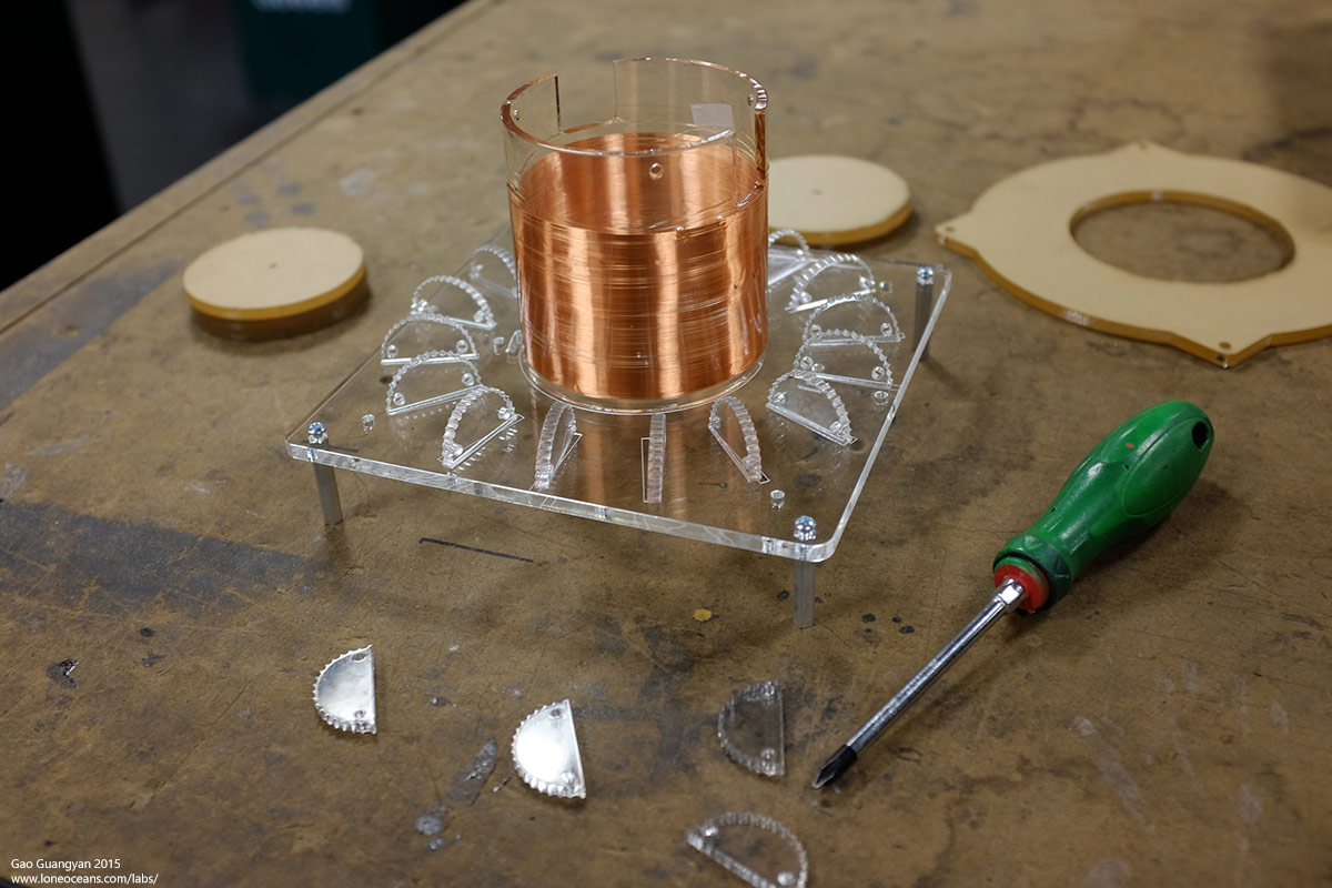
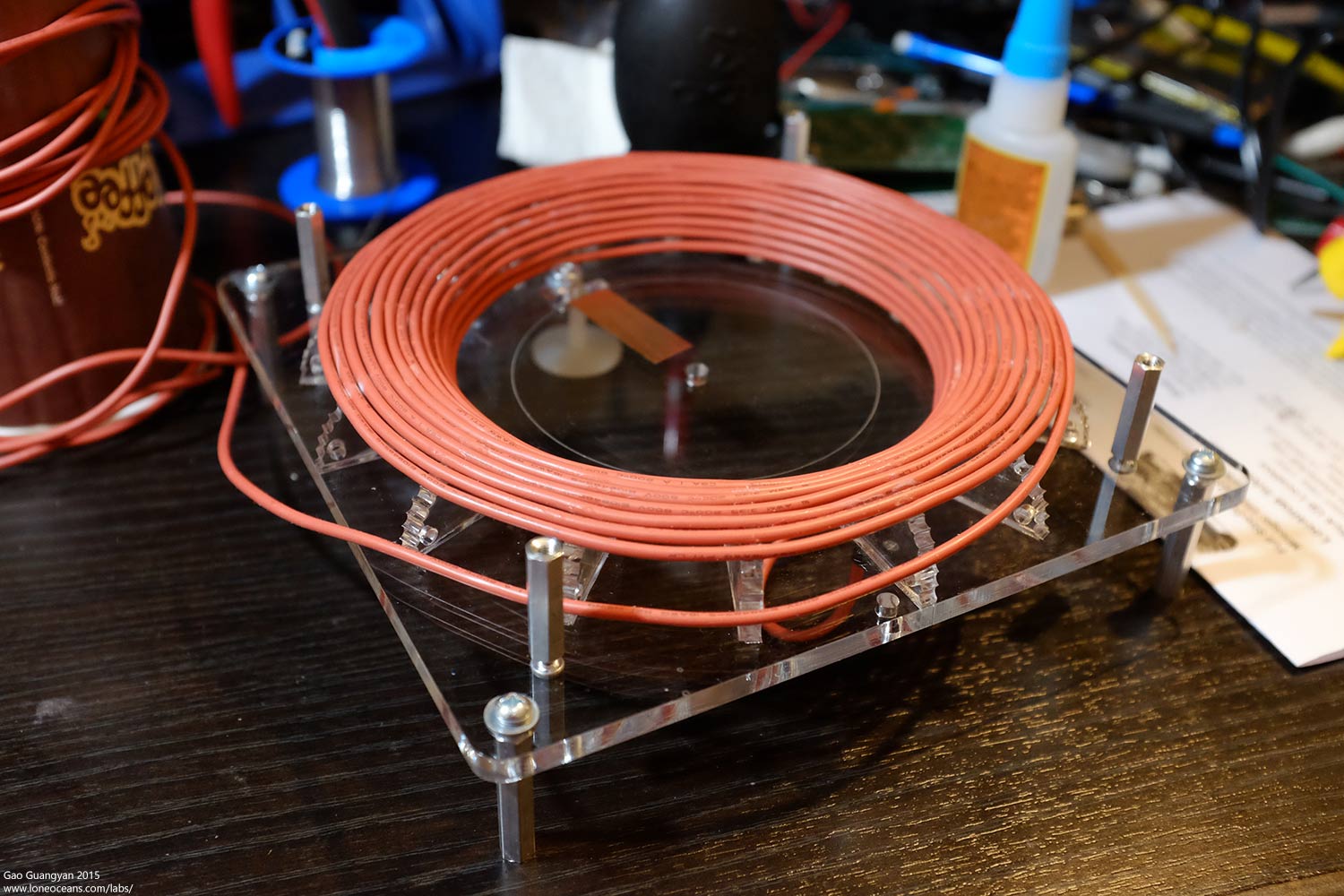
Coil Construction
Design of the coils was done in CAD and a laser cutter was used
to cut the primary supports out of acrylic. The primary coil was
then constructed carefully by gluing the primary coil to the
supports.
Next was to put together the power electronics and to
build a box to house them. This was fairly straightforward.
Once everything came together, I put the coil on the
bench for tuning and adjustments.
The coil is ready to run!
Results
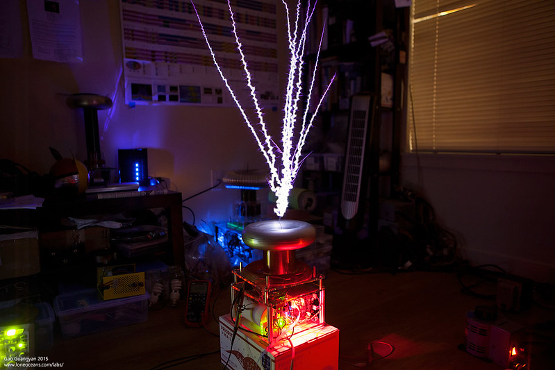
08 Nov 2015
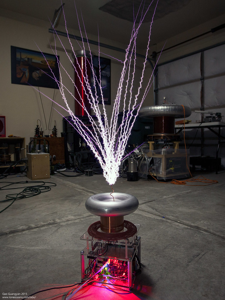
I was finally able to put the coil together -
the project turned out well in the end, with the coil making ~2
feet + sparks from a 2.4" secondary coil, so far running with
about 340VDC on the bus. Enjoy the photos / videos below!
And below is the coil in action with about 235VAC input
to the bus. with various pulse widths and ramp configurations.
The super high impedance primary circuit self-limits
current to around 50A. A long high-duty-cycle run was also conducted
with the coil drawing some 4.5A at 235VAC (though with crappy power
factor), and thermals analyzed using a FLIR thermal camera. The warmest
parts of the coil was the secondary coil getting up to over 60C, primary
~40C and the power electronics remaining pretty cold. Looks like I can
push the coil a bit more :-).
Above is another video of the QCW 2 in action running
similarly with a variety of pulse levels.
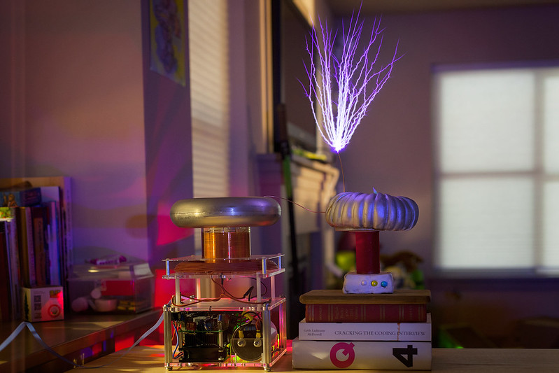
Finally, we answer the question - can we make a cake
make sparks?
Who knew that the answer is yes! Well technically the
QCW 2 is creating the spark - there is a wire which connects the metal
toroid to the cake toroid. The cake toroid is a regular moist cake
covered with silver fondant. The 'secondary coil' here is just a plastic
tube, sitting atop another 'base-box' cake. At the top of the cake
toroid, another wire was inserted in which acts as the breakout point.
The two wires were not connected. This cake was made by my talented
friend Wendy. The QCW 2 was then operated at regular mode. Notice how
much smaller the sparks are - this is due to massive de-tuning where the
resonant frequency was significantly lowered due to the extra 'toroid'
and capacitance provided by the cake.
In the end, I found that the area around where the two
wires were had some severe 'cooking' of the batter, but the rest of the
cake turned out just fine! Perhaps the next step is to adjust the
driving frequency to lower it, and this may produce better spark length!
As usual, more to come soon!
Back to main page
(c) Gao Guangyan 2025
Contact: loneoceans [at] gmail [dot] com
Loneoceans Laboratories. Copyright (c) 2003 - 2025 Gao Guangyan, All
Rights Reserved. Design 3.
Removal of any material from this site without permission is strictly
prohibited and will result in infringement of copyright laws.
Disclaimer: Projects and experiments listed here are dangerous and should
not be attempted.
www.loneoceans.com/labs/
... page generated in 0.00015 seconds