7W of 450nm Blue Laser Light
|
Project 450 - Building a High Power 7W NUBM44-V2 Blue Laser
Introduction
It has been several years since I last worked on any laser-related
projects. The first such project I worked on was back in 2006, where I
extracted a red 650nm laser diode from a DVD burner, resulting in a
Red Laser with about 200mW output. A few years later, I built a similar one
using a 405nm diode from a PHR803t module (used for Blu-ray discs),
resulting in a ~90mW Violet Laser. More recently in 2010, I put together
a really powerful one with a 445nm blue diode from a laser projector, this time
with the diode driven
at 1A and capable of about 1W of lasing output.
Safety Notice & Disclaimer
This project
involves dangerous laser devices which will cause serious injury
if misused or used improperly. If you proceed reading, you are
legally responsibly for any use of information on this page, and
any injury caused to yourself or anyone else resulting from the
use of information here. You also agree to treat the information
provided here with respect and responsibility. This page does
not advocate the use of these kinds of lasers at these power
levels since they are extremely dangerous and any mistake will
lead to irreversible eye damage or worse. Details provided in
this project page are meant as an educational engineering
resource. Laser goggles are always used (in this case a proper
5+OD for the wavelength goggles are always worn whenever
operated). |
Over the past (almost decade!), there has been great advances in LED and
laser technology, with blue laser diodes seeing large commercial use in
consumer and industrial projectors and small desktop laser-etchers. This
has driven the cost of these diodes down, and improved power density.
What is Project 450?
Project 450 is a compact, simple, fully-integrated, constant-current
driver platform for LDs (Laser Diodes) and LEDs (Light Emitting Diodes). This
project page focuses specifically on the design and development of the
drive electronics in order to safely drive a constant-current load (such
as this diode, or any LED for that matter), and is therefore applicable
to all sorts of similar projects. The number 450 refers to the
wavelength of the candidate diode.

In this project, I develop a compact constant-current synchronous-buck
battery-powered driver capable of driving a constant current load of up
to 12A with a total power of up to 50W. This driver is adapted for driving a specific TO-5 (9mm,
sometimes mistakenly called TO-9) package 450nm laser diode at 4500mA, achieving 7
Watts of lasing output (from about 21W power input). This page focuses on the design and development
of the main drive electronics in order to safely drive this diode.
 In this page,
I'll describe the engineering decisions and process for developing this driver. Hopefully this
will also be a useful resource for many like-minded hobbyists around the
world who are also fascinated by LEDs, LDs, and power electronics.
The Project 450 design including schematics, layout, firmware, and
architecture are available on this page under the
Creative
Commons License. In this page,
I'll describe the engineering decisions and process for developing this driver. Hopefully this
will also be a useful resource for many like-minded hobbyists around the
world who are also fascinated by LEDs, LDs, and power electronics.
The Project 450 design including schematics, layout, firmware, and
architecture are available on this page under the
Creative
Commons License.
Project Status
July 2019 - Some improvements: new batteries, and a
higher quality machined aluminium diode block to replace the
'red-copper' diode block. Project complete!
June 2019 - The project is officially completed and fully functioning.
Laser diode has been installed and verified with a 4500mA drive current,
21W power input.
01 Oct 2018
Optical Considerations
The heart of Project 450 is the laser diode.
The project came about due to the availability of some specific high-power laser diodes
which have emerged over the past years since my previous projects. Here we'll take a quick look at some
common diodes available today (as of end 2018), and how we arrive at our final candidate
laser diode.
Choice of Laser Diode: NUBM44-V2
In all of my previous builds, the laser diodes used
came in a TO-18 package, which is a 5.4mm diameter metal case
package (commonly also used in transistors, but the laser diode package
often has a thicker metal base for heat-sinking).
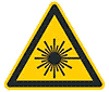
TO38, TO18 and TO5 laser diode packages showing their different relative sizes
(image retrieved from
here).
As we increase in power levels, the size of the diode
and package increases due to heat dissipation requirements. The diodes
we will discuss below are some of the popular diodes that
have came on the market since my previous project, and we will be
looking exclusively at those in a large TO5 9mm package, as well as
comparing it with my previous Project 445 build using the 'A140' TO18 diode.
2W M140 445nm TO18 (DTR)
- 2010
The A140 and M140 are 445nm TO-18 blue laser diodes which
appeared around the market around 2010 or so, in consumer projectors.
There was complicated event which occurred during that time with a
certain projector and electronics manufacturer, and as a result, the
related manufacturer and their products are not named. Therefore these
diodes are referred to as the 140-series diodes. The A140 diodes first
appeared, followed by the M140 diodes a few years later. To make things
more complicated, there are also several variants of the M140 diode,
described on DTR's page.
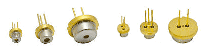
Beautiful close-up image of the die and different bond wires of the A140
(3 wires) vs M140 laser diode (4 wires), retrieved from
DTR's page.
In short, the A140 diodes while very good, are not as
powerful as the M140 diodes. They can be distinguished by a spot printed
on top of the tiny QR code on the bottom of the TO-18 can (where the
A140 diodes do not have it). Regardless, for their time, the A140 diodes
caused quite a stir, being easily capable of 1W output. The differences
between these diodes are discussed on the LPF forums
here.
The M140 diodes brought that up a notch achieving about 2W
output at 1.8A using a G-1/2 lens (as tested by DTR), which is the
maximum suggested running current. To keep things in perspective, in my
previous Project 445 build, I drove a A140 diode around 1050mA via a
LM317 linear regulator and 3 CR123/16340 batteries, for a total of 1W
lasing
output.
4W Nicha NDB7A75 445nm (DTR)
- 2013
This diode appeared on the market some-when around 2013,
and had a datasheet rating of 3.5W output at 448nm (typ) at I_fwd of
2.3A. When it first came on the market, it stirred up a
big interest among hobbyists since it had almost twice the rated
power as the previous popular NDB7875 diode. DTR from LPF conducted an
array of tests on this diode and concluded that it ran at 3.5A
(4.80W) comfortably, and even 4A (5.22W).
This is one of the few high power diodes of which the
actual part number is known and the basic
datasheet is available. The diode has a typical threshold lasing
current of 270 (200-350)mA, producing 1.7 (1.5-2) W/A, and a beam
pointing accuracy of +-3deg.
6W NUBM44-71 / NUBM47T / NUBM44-V1 450nm (DTR)
- 2015~
This diode (both this V1 and the V2 below) appeared on the market in
middle of the 2010s. Similar to previous diodes, they were harvested
from commercial projectors. When these diodes first appeared, they again
caused quite the stir among the laser community for their much improved
output compared to the NDB7A75.
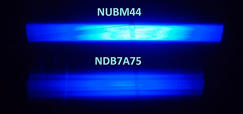
Beam profile comparing the NDB7A75 with the NUBM44-V1, taken by DTR on
LPF
The reason for the unusual name comes not from their
part number (which is unknown, but known to be produced likely by
Nichia), but rather the number printed on the laser diode array assembly
they come in, in this case, NUBM44-71. After a fair bit of testing, it
was determined that those trays labeled with NUBM47T were likely
carrying identical diodes, and thus they have been classified as the
same.
The NUBM44-71s come in a 8-bay block, and appear to have
a higher wavelength of about 450nm instead of the previous 445nm diodes. With
extensive testing on the forums, it's been determined that the diode
does very well up to 4.5 to 5A of current drive, capable of 7W of output
power.
7W NUBM44-81 / NUBM47-A1 / NUBM44-V2 450nm (LPF
&
LPF &
DTR)
Close-up of the die of the NUBM44-V2 taken by
ABarnett
The NUBM44-81 or 47-A1s, unlike the V1s, come in a
10-bay block. While almost essentially similar, they appear to be
slightly more efficient. It has been guessed that
these diodes are likely identical to the 44-71 diodes, just higher
binned. According to tests by DTR, they seem to be about 10% more
efficient.
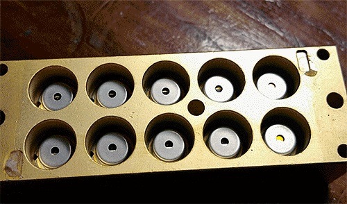
Above shows an array of 10 9mm TO5 laser diodes - the bare diodes are
difficult to buy in small quantities to consumers. Instead, they are
often
carefully 'harvested' from high power projector modules. The diodes are
heat-sunk into the frame, and often come in 8x or 10x arrays. Image from
here.
In order to make the distinction clearer, the community
often refers to them as NUBM44-V1 versus V2. The V2s easily push past 8W
in tests, with Alex Barnett acheiving some
10.39W at
5.4A/5V after freezing the diode.
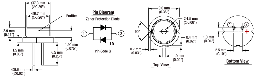
9mm TO-5 Package drawing for NUBM44-V2 Laser Diode, note Cathode and
Anode positions. Image from generic TO-5 datasheet from
here.
The choice is clear then - we'll pick the most powerful diode available,
the NUBM44-V2. Above we can see the size specifications of the diode,
and pin 1 here is the Cathode of the diode.


Being less than enthusiastic about
extracting my own diode from a heat-sunk array, I was able to source one
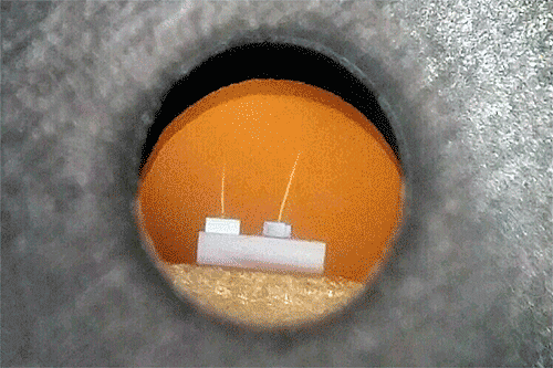
online for $74.95. Above shows two photographs of the diode. In the top,
you can make out the actual diode mounted on the heatsink through the
window of the TO-5 can, and the bond wires to the diode. The bottom
shows what appears to be a QR code.
Drive Characteristics
I decided to compare the M140 diode with the NDB7A75 and
NUBM44-V1 diodes (with the V2 given a 10% increase over the V2 since I
could find no hard data). The results are presented in the chart below.
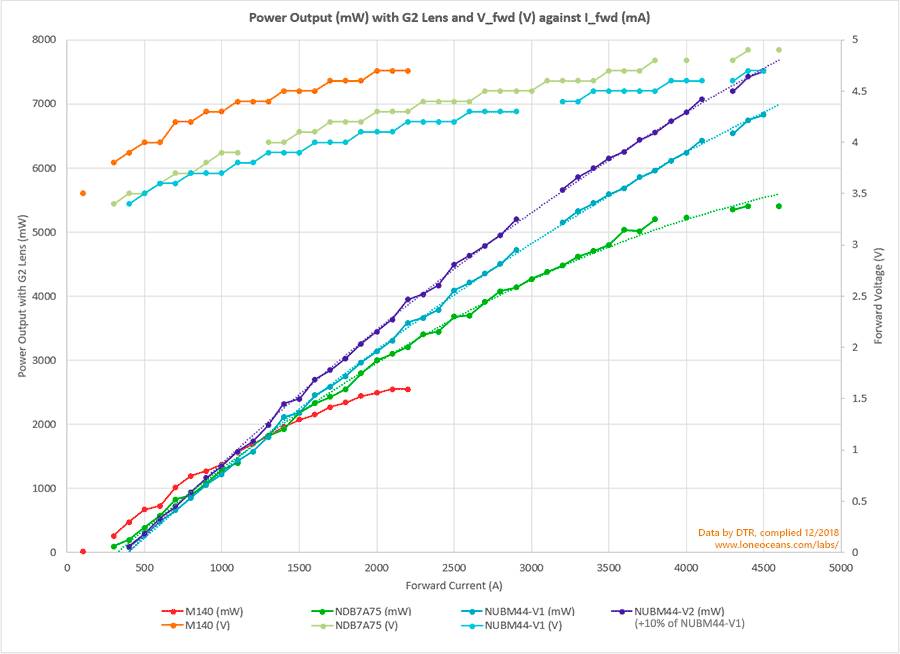
Chart showing power output and forward voltage of 3 diodes (+1 assumed
to be 10% more efficient) against forward current; data by DTR.
I created the above graph (many thanks and all credit for the data
goes to DTR for his hard work characterizing the different laser diodes),
and this
shows some interesting trends, and allows us to determine the operational
characteristics of our NUBM44-V2 diode. For one, looking at the V_fwd,
we can see that for a fixed forward current, the forward voltage of the
diode is dropping as technology improves, from the M140 diode to the
NUBM44.
Next, we see that the M140 begins lasing as low as 100mA
with 22mW output, as compared to the NDB7A75 starting at 300mA (97mW, in
line with the 270mA datasheet threshold), and the NUBM44 starting at
400mA (with about 90mW output). DTR has run the NUBM44-V1 at 5.5A for a
whole 2 minutes with no drop in output power, suggesting that the diode
is in fact capable of more than 7W, or even 8W.
We now have the following (admittedly arbitrary) operational levels for
driving the diode:
- Threshold - <100mW (400mA at 3.4V)
- Bright - 500mW (600mA at 3.6V)
- Powerful - 2000mW (1350mA at 3.9V)
- Turbo - 7000mW (4.2 to 4.6A (4.5A) at 4.7V)
We will use these values when configuring the driver.
Optics
For best optical power output, a single element G2 lens is used.
I purchased this from barnett_unlimited on
eBay
for $14.95.
This lens features a M9x0.5 thread for standard 12mm modules
(as well as the diode block I will be using), and has an AR coating for
405nm - 520nm. Front and back focus are quoted as 4.02 and 4.8mm,
transmission of 98%, 2.357mm working focus, L-BAL35 glass type, and is
best suited for engraving.
A 2 or 3 element glass lens will be better suited for
longer distances though.
Another great option is the 'DTR-G8-Collimating Lens",
offered by
DTR. As described by him, "this lens is a long focal length single
element glass lens with a broadband 400-700nm AR coating. It has a 90%
pas efficiency which is amazing for a longer focal length lens. It does
an amazing job of cleaning up optical aberrations around the projected
spot caused by stray light reflecting off the edge of the emitter or in
the lens barrel. This what is seen as box shape that is projected under
the spot created on single element lenses with the newer very high power
diodes. It creates a greatly reduced spot size while maintaining a 90%
pass efficiency compared to the 96% pass efficiency of a DTR-G-2."
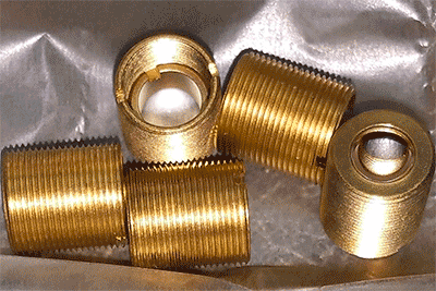
Thermal Considerations
For the thermal assembly I opted for a red-copper diode
block.
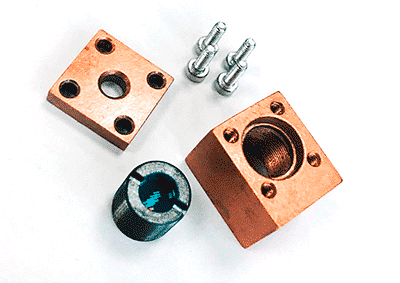
I was able was able to get this product from techhood on
eBay
for $10.35 which included a standard 405-470nm AR coated glass lens
(MP905x8mm). The 13x12x15mm copper block allows a press-fit for the
TO5-9mm diode, and has two mounting screws on the bottom. This included
lens will do well for standard usage, at the cost of reduced power
output due to losses in the optics (which will be upgraded to the ones
described above).

This copper diode block as well as the main PCB will be
mounted on a 5mm thick aluminium plate, which will act as the
superstructure, as well as the main heatsink for the entire device.
Since there is no plan to run the laser continuously for more than 10s
of seconds at a time, this design will work just fine with no danger of
thermal overload.
Electronics Design
Laser diodes are similar to regular LEDs in a few
aspects. First, there is a starting lasing threshold - a threshold voltage for
LEDs, and a threshold lasing current for Laser Diodes (LDs). Second,
these diodes have a fairly steep IV curve - once the threshold operating
point is reached, a small increase in voltage results in a
disproportionally large increase in current. Furthermore, this
characteristic fluctuates greatly not only with operating conditions
(such as temperature), but also varies from die to die. Finally, these
diodes have a negative temperature coefficient - an increase in
temperature leads to a drop in forward voltage, and therefore a rise in
current. As a result, when driven from a constant voltage source, LEDs
and LDs can quickly overheat, enter a dangerous positive feedback cycle,
leading to thermal runaway and ultimate destruction of the diode.
Using a resistor is common way of limiting current to
LEDs, and can also be used for LDs. Resistors however are inefficient,
especially as power levels increase. Therefore the sensible way to drive
high power LEDs and LDs are carefully designed regulated constant-current drivers.
Linear constant current drivers as used in my previous
projects act essentially as 'adjustable
resistors', and power is dissipated in a pass transistor (acting as the
'resistor'), but have additional functionality over simple resistors but
allowing adjustable current
control.
To improve efficiency, a switching DC-DC converter can
be used instead. A feedback loop senses the forward current, and then adjusts the output voltage
of the DC-DC converter accordingly to maintain that current. It is
possible and in fact easy to design DC-DC converters with over 90%
efficiency, so this approach is significantly more efficient than a
linear driver, at the added cost of complexity. This will be the
approach we will be taking.
Having had some experience with my recent flashlight LED
Driver projects (such as the GXB172 50W
flashlight driver), we will
now apply the same ideas and learnings for this project. Before we
begin, let's take a look at some of the popular switching
constant-current regulated drivers used by hobbyists today (at time of
writing). Most of these are buck-type step-down drivers, taking power
from an array of lithium batteries (typically 2S or more), or an external
power supply.
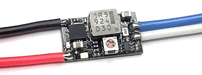
What Drivers are Available Today?Super X-Drive
5.5A - $26
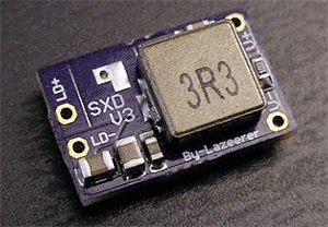
The Super X-Drive (SXD)
V3 )
V3 is a 10.3 x 15.4mm buck driver by Lazeerer. It's available on eBay or
on DTRs shop for $26. It features adjustable current control via a 5V
1kHz PWM modulation (or simply a resistor), with an absolute maximum of
12V input. It has a listed 1.6V threshold for enable, maximum of 5.5A
output. The main switching converter is a 8-SOIC part, and based on the
specs listed, is very likely a Texas Instruments
TPS54628 or one of its variants - a simple 4.5 - 18V 6A synchronous buck
converter IC with integrated 36mR and 28mR FETs.
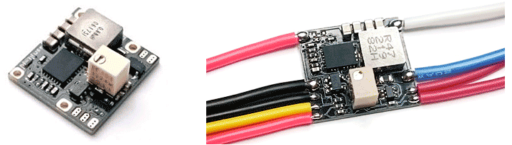
ACS5500BU 5.5A Driver - $29
The
ACS5500BU Rev 2 driver sold by x-wossee on
eBay and
DTR is a 10 x 16mm driver in a form factor and layout which I can
appreciate (looks well designed). It is available for $29, and replaces its predecessors - the BlackBuck 3 and 6. The board has a very compact and single-sided layout
(allowing for easy heat-sinking), features a 'high-side' design,
soft-start, ceramic fuse, and sensible output and input pads. The supply
voltage is rated 6 - 14V, load 1.5 - 6V, 250ms SS, 140C thermal limit,
and 5.8A output. Current adjustment is done via an on-board trimmer
resistor, and the board features a 5V-tolerant enable pin. The sense
resistor appears to be a 10mR resistor with some sort of SC70 op-amp as
the current sense amplifier or similar for CC regulator.
Based on the description and unusual physical
characteristics, it's pretty easy to guess that the main switching IC is
the nice Richtek
RT7298B HGQW, a 3.5 x 3.5 14 QFN 6A 18V synchronous buck converter,
featuring 26/19mR internal FETs, adjustable soft-start ($3.09 in 1x qnty
on Digikey). One feature I like about the ACS5500BU is that it has
exposed ground pads on the bottom, allow good heat conduction with a
heatsink. The ACS4500BU is a similar driver ($29) and is essentially the
same, but with a slightly lower profile (likely smaller inductor), and
1A lower power handling capability.
BlackBuck 8M Rev 3 8A Driver
The BlackBuck 8M Rev 3 sold by x-wossee on
eBay and
DTR for $39 is the larger cousin of the ACS5500BU. It shares a layout and design, but improves on its power handling
capabilities. The 8M takes in 7 to 12V, with an output of 1 to 8A, 100us
rise time, 0.5ms startup delay, includes pads for external current
control via 5V PWM or a potentiometer, has an on-board trimmer, and also
has temperature cut-off via an external 3950/10K NTC (or can be uses as
an interlock, short to disable), all on a compact 17x16mm PCB.
Based on the description and the fact that the boards
has a 5V reference output, the BlackBuck almost certainly uses the
International Rectifier
IR3475 10A integrated SupIRBuck regulator ($3.58 on Digikey in 1x
qnty). This 4x5mm 17 QFN features 3V-27V input, 0.5-12V output, 10A load
capability and 23/13mR internal FETs. The SOT23-5 device on the board is
likely a 5V regulator (hence the 7V minimum input, and this powers the
VCC rail of the IR3475), and the SC70-5 package is likely some sort of
amplifier for current sense.
With the above as an inspiration, let's see if we can do
one better without spending too much money.
Synchronous Buck Design - TPS56C215
When designing the driver for this project, I was
initially thinking of using the Texas Instruments
TPS565208
buck converter ($2.14 in 1x).
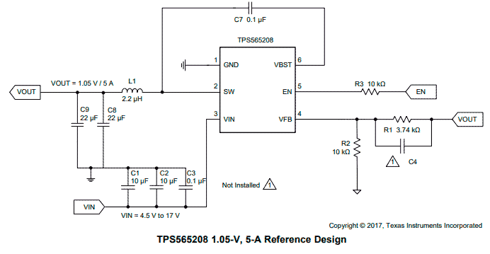
TPS565208 reference design from TI's datasheet of this IC
It is super simple and easy to use and set
up, has a good 4.5-17V input, and is capable of 5A output with 31/16mR
internal FETs. This will be sufficient to power our laser diode
(at 4.5A). It also comes in a cute and friendly SOT23 package. However,
why stop at 5A when we can go all the way to 40A? The Texas Instruments
TPS548D21 is a 1.5 to 16V in 40A converter and
still comes in a small 7x5mm 40QFN package, including 2.9/1.2mR power
FETs! However at $10.89 per piece (at 1x qnty on Digikey), it is
definitely excessive in every sense of the word.
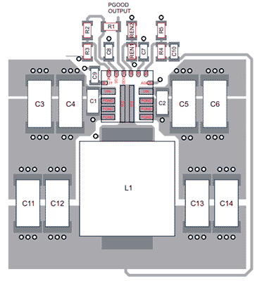
Suggested layout of the TPS56C215, from TI's datasheet of this IC
Sensibility got the better of me and I eventually
settled on the
TPS56C215RNNR ($4.56) 3.8-V to 17-V Input , 12-A Synchronous
Step-Down converter. Being TI's smallest monolithic 12A IC, it measures
just 3.5 x 3.5mm, and comes in a well designed VQFN 18 'hot-rod'
package. This design allows for a very clean and compact layout as shown
above, as well as having excellent thermal properties. The TPS56C215
features integrated 13.5 / 4.5mR FETs, 0.6 to 5.5V output, 4.5Vmin start-up
without external bias, optional external bias for improved efficiency
and an adjustable soft-start. Its 12A current capability means that
it's good for some 50% more power handling capability than the
BlackBuck8, while being more efficient (better FETs), and more compact.
This shall be our sensible IC of choice. Next time we
build a bigger one :-).
Requirements
The requirements for this design can be summarized as
follows:
- Input: two CR123A / 16340 lithium batteries, 6Vmin to
8.6Vmax input
- Output: 100mA? (depends on threshold lasing current) to 6000mA
We will design for 5.5A max output for now for the safety of our NUBM
diode, but this design will easily allow us to go to 12A --> 50W of
power!)
- True constant current regulation
- ~250ms s- ~250ms soft-start
- 3.4V to 5V output
With the requirements in mind, we can begin our design.
Fortunately, TI has an excellent
online tool to help us with our design. It works really well, so
hats off to the engineers who developed the tool. I started a design
with 6-8.6V input, 5V at 6A output, 30C parameters, and generated a
reference design.
Switching Regulator WEBENCH Power Designer
Using the online tool, we quickly generate our design.
The design suggests one of my favourite inductors as the main buck
inductor, being the Coilcraft XAL7030 series in 3.3uH flavour, having a
DC resistance of 19.5mR and an I_sat of 12.3A. For even better
performance, we can switch to the XAL7070 series which will improve
efficiency even more by dropping the DC resistance to 8.56mR (I_sat of
19.4A), at the cost of increased size.
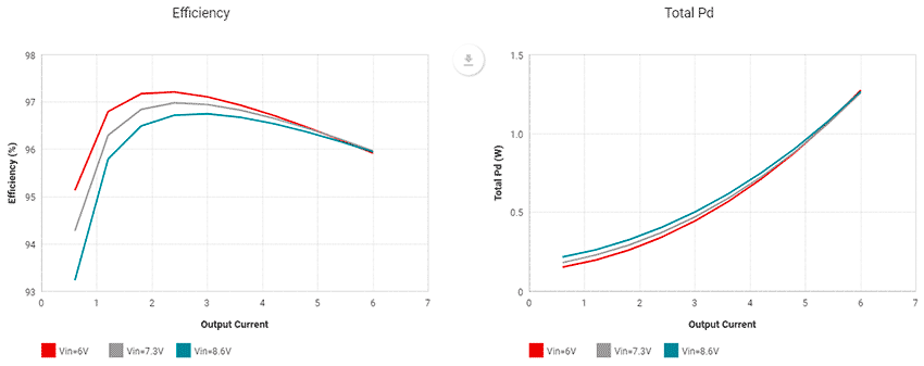
Efficiency and power dissipation simulation using TI's Webench with the
parameters described.
With the 7030 inductor, the results are pretty good,
with a design capable of >95% efficiency throughout most of the range.
Inductor power dissipation is a maximum of 706mW with 1.57A peak ripple.
IC power dissipation is calculated to be about 955mW for a total of
1.66W dissipated including passive losses. Switching to the XAL7070
drops inductor losses to 311mW, resulting in a total 1.27W power
dissipation.
The generated design calls for light load operation of
FCCM (instead of DCM, to maintain a constant switching frequency) and
current limit of ILIM (vs ILIM-1) and a switching frequency of 400kHz.
For the SS pin, the equation for calculating is C_ss = (T_ss * I_ss) /
V_ref, where I_ss = 6uA and V_ref = 0.6. Given a 200ms desired ramp,
C_ss = 2uF. The recommended output capacitor is 88uF, and 40uF for the
input side, with equal caps on each side of the IC.
Here are some additional layout guidelines:
• Recommend having equal caps on each side of the IC.
Place them right across VIN as close as possible.
• Inner layer 1 will be ground with the PGND to AGND net tie
• Inner layer2 has VIN copper pour that has vias to the top layer VIN.
Place multiple vias under the device near VIN and PGND and near input
capacitors to reduce parasitic inductance and improve thermal
performance
• Bottom later is GND with the BOOT trace routing. Feedback should be referenced to the quite AGND and routed away from
the switch node.
• VIN trace must be wide to reduce the trace impedance.
Finally, the entire system will be controlled by a small
Atmel ATTiny microcontroller. This MCU will handle the different current
modes, as well as display useful information such as battery status,
power setting, and so on.
Battery Choice
The choice of battery size is the CR123-size, which is
typically non-rechargeable; or alternatively known as 16340, which is
the rechargeable variant. This size was chosen for its compact
dimensions, and mostly because I had a bunch of Lithium CR123 cells
lying around, as well as several EBL-branded 16340 cells. At the
expected load of just over 20W, the expected cell current (two in
series) should be between 2.5 to 3A.
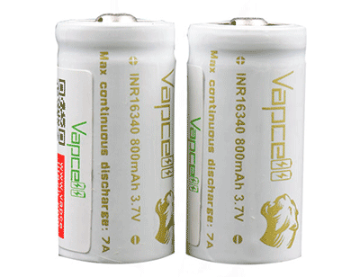
Picture of the white INR16340 cells from Vapcell, image from Vapcell's
website.
The red EBL-branded cells handle 3A with no issues, but
the current best 16340 cells I can find on the market at time of writing
at the
Vapcell INR16340 (white) cells. These have a rated capacity of
800mAh, and are rated 7A discharge, and as measured by HKJ, are
currently one of the best 16340 cells at time of writing.
In fact, comparing with larger 18350 cells, they
certainly hold their own at high discharge currents. While the target
diode only requires 20W drive at this time, the driver is technically
good for up to 50W, so it will be nice to have the option of future
upgrades.
For the record, at time of writing (early 2019), the
best performing 18350 cells are:
-
Shockli 18350 1150mAh Black
-
Vapcell INR18350 1100mAh Purple
-
Keeppower 18350 1200mAh UH1835P Black
Peripherals - USB Charging
I wanted to add an additional micro-USB charging
capability to the project for ease of charging the batteries. The
batteries I plan to be using are two 16340 lithium cells in series with
a maximum charge voltage of 8.4V for both of them in series. The goal
was a
charge time of about 1hr. 16340-sized batteries typically come in about
700mAh capacities, so the target charge current will be 700mA.
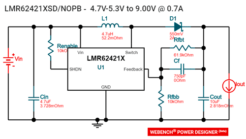
Automagically generated design using TI's Webench Power Designer using
the LMR62421 Simple Switcher.
We get an excuse to use a super cute 4020 inductor
from Coilcraft as the boost inductor!
The first step calls for the TI
LMR62421 Simple
Switcher 2.7V to 5.5V, 24Vout, 2.1A Boost Converter in SOT-23, boosting
5V from USB, to 9V. While not the most efficient (since it is
asynchronous), it's simple and easy to implement, with a simulated
efficiency of >88% at 700mA output. This 9V rail feeds into a TI
BQ2057W Low Dropout
Linear 2-cell Li-Ion Charge Controller with a PFET pass element for
linear charging. A safety interlock with the Atmel MCU prevents turning
on the laser diode if charging is in progress. The PFET will be the main dissipative element during
battery charging.
Next, the design. We first determine the maximum power dissipation in
the transistor. The worst case happens when the batteries are fully
depleted at 3V each, the charge current is at maximum of 700mA, and
input voltage is at its maximum 9V. Then power dissipated = (9V - 0.125V
- 6V) x 0.7A = 2.0125W. 0.125V is the voltage dropped across the current
sense resistor.
The minimum theta_junction_to_case can then be calculated using
the maximum junction temperature (usually 150C), the ambient temperature
(usually 40C) and the power dissipation. Hence theta_jc = (150 - 40) / 2
= 55C/W. We will find a package that has a lower theta.
Next we calculate the required gate threshold using V_gs
= (0.125 + 1.5) - 9 = -7.375V. Here 0.125V is the voltage drop from the
current sense resistor and 1.5V is the CC pin output low spec of the
BQ2057. Any PFET with a V_gs within -7.375V will work (should should be
plenty). For current handling capability, we simply give us a 2x buffer
at >1.4A. Finally, any device with greater V_ds than 10V will work fine.
After a parametric search for parts with VDS <= -20V,
theta_JC <= 55C/W, I_D >= 1.4A and V_GSth >= -7.375, I chose the
SI7615CDN for it's impressive -20V 35A capability, and outstanding
junction to case of 2.9C/W, an order of magnitude better than SO8
packages despite its much smaller size.
SchematicThe follow is the schematic for Project
450 for reference.
The schematic will be updated here soon. Please check
back frequently!
The Project 450 design including schematics, layout, firmware,
and architecture are available from this website under the
Creative Commons License.
Layout
With the electrical design done, it was time to do the
layout.
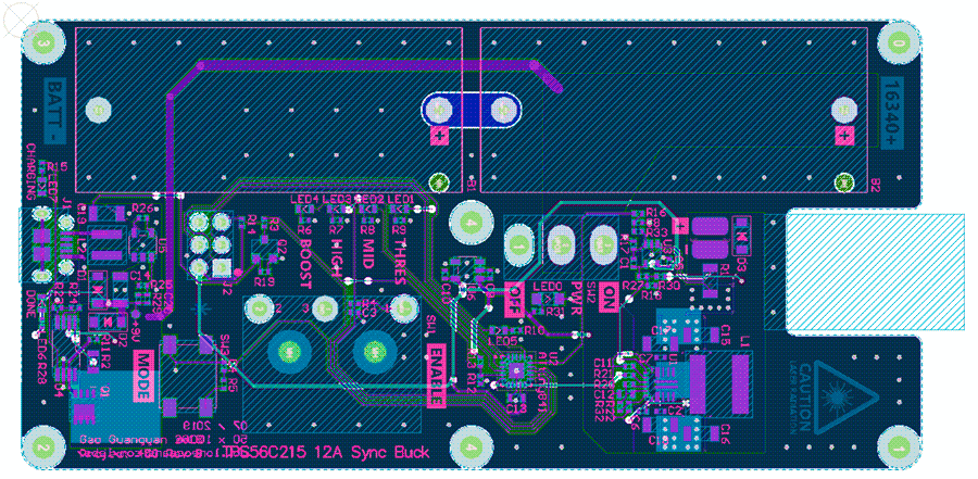
The layout was constrained to fit on a 100x50mm board
outline, whose size was dictated by the battery holders. Layout was
fairly straightforward due to the large amount of space on the board.

Above we can see a render of the completed layout.
The
left side consists of the 9V boost regulator, as well as charging
circuitry. The right side consists of the constant current buck
regulator, and a ATtiny microcontroller sits in the middle. The
microcontroller handles the entire system for various kinds of events.
Here are a few features:
- Security Safety interlock requiring secret code to
be entered via switches before system unlocks, impossible to turn on in
a bag
- Constant current control with 4 programmable constant current power
modes
- Battery monitoring and low voltage cut-off
- Charge management
- Error codes via a total of 5 colourful LEDs
Thermal handling was also incorporated into the design.

To heat-sink the switching regulators and the battery
charger, the entire PCB only has components on one-side, with exposed
ground pads on the bottom as can be seen above. The PCB is screwed onto
a milled aluminium baseplate, whereby the exposed ground pads allow
thermal connection to the baseplate.
To prevent shorts, holes are milled into the baseplate
for through-hole legs to sit in. A kapton sheet was then laser-cut to
insulate all other parts, and thermal paste was then applied to the
exposed ground copper pads to interface with the baseplate. A cutout in
the PCB allows the diode, housed in a solid copper mount, to be attached
directly to the baseplate.
Assembling the PCB
The PCB was fabricated to be 1.0mm thick. Once they
arrived, I was able to quickly get the board soldered up. In addition, a
piece of 5mm thick 6061 aluminium stock was cut to 50 x 100mm size, and
carefully milled, drill and tapped to accept 8 mounting threaded holes,
and several more milled cutouts for through-hole components.

Above shows the result of the completed and assembled
board with all components installed. It's nice when the project finally
comes together and looks exactly as envisioned! A few small errors in
the first revision led to an updated Rev B PCB, with all functions
tested to be working with no further errors.


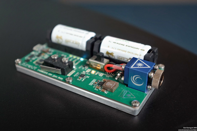
Above shows the completed project with EBL-16340
batteries, and with all 6 LEDs illuminated (4 cyan mode LEDs, one warm
white power LED and one orange debug LED). In addition, a red and green
LED indicate charging status when a USB cable is plugged in (for battery
charging).
July 2019
Tweaks and Improvements
Here's
a quick update since the completion of the project. I've since updated this build with an improved diode
host.
Project 450 now uses a very well machined aluminium diode block made by
Lasertack from Germany. Thermal performance is in fact much improved,
since there were concerns about the (relatively low) quality of the 'red
copper' material used in the original diode block.
In addition, I've upgraded the batteries used in the project.
The red 'EBL-brand' cells have been swapped out for some of the best 16340 cells commonly
available - the white Vapcell NR16340s (see the test here by
HKJ). They
were verified to have absolutely no trouble supplying the ~20W required
in this build. This marks the completion of this build and I'm quite
happy with how this came out.
Results
Jun 2019
Project 450 - first light & comparison with 1W A140 build

Above shows Project 450 in action! In this photo, notice
the power level is set to 'Medium level', or a 500mW output. In order to
make the beam more visible, some water droplets were sprayed.
More photographs of higher quality to come soon! The
driver was tested together with the NUBM44-V2 diode all the way up to
the 4500mA operating current, with excellent results.
More to come soon - please check back frequently!
Useful Links
Community References
DTR NUBM44 - DTR's page on this laser diode and associated
BLF page
DTR 8A BlackBuckM - a small 8A Buck converter for laser
drive
NUBM44-V2 - LPF page on this diode
Barnett_Unlimited - is 'not a scammer'!
EE Components and Datasheets
Digikey - DC-DC Switching Regulators
MPS - MPS DC-DC Switching Regulators
MIC24056 - Micrel 12V 12A Buck Converter 5x6mm
TPS54821 -
TI 17Vin 8A Sync Buck 26/19mR 3.5x3.5mm QFN14
TPS568215/OA - TI 17V 8A Sync Buck 19/9mR
3.5x3.5mm QFN18 DCap3
TPS53318 - TI 25V 8A
Sync Buck 5x6mm
TPSM84824 - 17V 8A
Buck Power Module in 7.5mm2 Footprint with Inductor
IR3841MPbF - IR 16V 8A Sync Buck 17/9mR 5x6mm
MP877x - 17V 10A Sync Buck 17/8mR 3x3mm
MP2639A - MPS 2S USB Battery Charger
NDB7A75 - Nichia 3A 450nm Laser Diode Datasheet and
LPF discussion
Digikey - Slide Power Switches
LM317L - 100mA
SOT89 CC Regulator
Designing a CC Buck Converter - TI Application note
Back to main page
(c) Gao Guangyan 2025
Contact: loneoceans [at] gmail [dot] com |