loneoceans labs | Dual Channel MIDI DRSSTC Controller - MIDI2 (temporary placeholder page)
Oct 2020 - Over the past half a decade, the MIDI2 controller has made its way around the world and has been a fairly popular MIDI controller for DRSSTC enthusiasts. To everyone who has purchase a MIDI2 controller, thank you for your support, and I hope it has been a useful controller for your projects! The last of the MIDI2 boards that I produced have since been sold. As of writing, there are no plans to continue producing this board. Each board was hand-assembled and tested, and this takes significant resources. However, there are in fact plans to produce an updated revision. The goal will be to keep the same features, but add some improvements and integrations, and to keep the cost a little lower. There is no timeline yet, but please check this page often for updates. Thank you.
 The Dual Channel MIDI Controller
(a.k.a. MIDI2) is
my Generation 2, no-frills yet full featured Tesla Coil
musical controller/interrupter designed for high performance DRSSTCs.
The Dual Channel MIDI Controller
(a.k.a. MIDI2) is
my Generation 2, no-frills yet full featured Tesla Coil
musical controller/interrupter designed for high performance DRSSTCs.
It interfaces perfectly with the UD2.7 Tesla Coil driver. The MIDI2 controller supports both standalone, and MIDI operation. It has a dual MIDI channel output for control of two different Tesla Coils independently (4 available outputs in total, two pairs of mirrored outputs). Each channel also supports a full host of MIDI effects including velocity, pitch bend, volume, and two-tone polyphony per channel, for a total of 4 tone polyphony when operating two coils!
Please scroll down for sample videos of this controller in action, with actual DRSSTCs.
In addition, the MID2 board offers a standard interrupter controller mode (individually toggle-able for each of the two outputs) with adjustable Pulse-Width (PW) and Frequency (beats-per-second BPS), and is designed to be simple and straightforward to use.
I developed this controller a while back for my own coils and have used this extensively over the past few years across a variety of coil sizes, platforms, and it has proven to be a simple, robust and reliable controller. This controller is now available for sale due to very popular demand.
The Dual Channel MIDI Controller is designed primarily for optical output and fiber-optic interface with the coil, but can also interface directly with most DRSSTC via a 5V enable signal. Optical control is recommended for noise immunity and electrical safety. This controller comes with the following features:
This controller has been tested extensively on small 800kHz DRSSTCs to large 20kHz DRSSTCs with excellent results, and have been used in many coils around the world to date!
Overview
This controller aimed at the advanced coiler looking for a simple but powerful controller for their DRSSTC. She/he should be experienced enough to debug the controller and interface it appropriately with the coil. The intended operation of the controller is to interface with the coil driver (such as the UD2.7) via a fiber-optic link of your choice. This provides both electrical isolation for safety, as well as noise immunity in the high EMI environment of a Tesla Coil. It is possible to use the output signal to interface directly with say a 5V TTL enable line on your driver, but this is not recommended over optical isolation.
What is Included
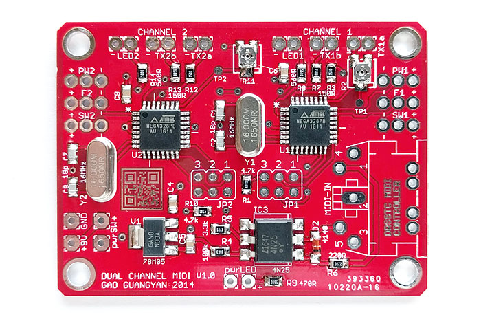
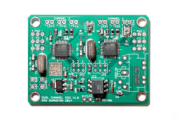
The interrupter/controller consists of 1x Populated, Soldered and Programmed Dual Channel MIDI Controller v1.0 as shown below, flashed with the newest stable firmware. This controller without the Add-on Pack does not include the MIDI socket. Note that the PCB soldermask colour depends on popular requests that I receive and can range from green, to red, blue etc; please check before you place an order. MIDI2 controllers will come packaged in an ESD-proof bag. Please take care when unpacking since microcontrollers are on board, and can be easily damaged via ESD.
Add-on Pack (optional, available while stocks last)
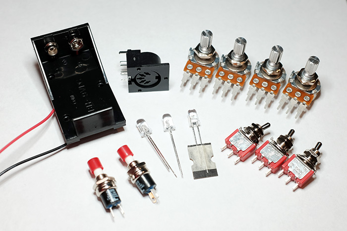
The add-on pack contains the basic and necessary components to get you started to assembling your controller, and as shown in the photo above. I am offering this add-on pack at essentially cost price for your convenience (subject to availability). If this is not available, the part numbers are also provided. Feel free to order at your favourite electronics supplier such as Digikey, Element14 or Mouser etc, or replace with a similar component of your choice. These part numbers are available on www.mouser.com (as checked on Jan 2018).
Items Not Provided in the Add-on Pack
You need to provide these items yourself to complete the controller, which will differ for different users:
All boards come populated as shown in the photographs above; microcontrollers on board are programmed with the latest stable firmware.
The MIDI2 Controller is sold out.
Please see the top of this page for the latest updates.
Dual Channel MIDI Controller "MIDI2" - (Assembled
and Programmed, Red Soldermask)
without add-on pack - $65 USD
(Oct 2019 - Sold Out)
Note that MIDI
5-pin Input Sockets do not come with the controller
Please read below for usage instructions
Dual Channel controller Add-on-Pack (sold at cost) - $20 USD (Out of
Stock)
Controller + Add-on Pack Combo - $82.50 USD
(Out of Stock)
ST fiber transmitters may be available upon request for $25
a pair due to bulk
pricing (usual $16+ ea.) (Out of Stock)
Latest firmware revision: V1.4 (Most stable version proven since 2014) - Valid as of Oct 2018
Shipping and handling for local US orders starts at $9.00. Will ship internationally. All boards are programmed and verified working before shipment. However, the buyer accepts all risk and consequences in operating the controller with the coil and will be fully responsible for self-testing and operating the controller in the intended operating coil system, and responsible for ensuring that the controller is compatible with the coil system.
Contact loneoceans [at] g mail [dot] com for enquiries and orders.
Putting It Together
This controller is designed for the advanced coiler so you should be able to troubleshoot the controller yourself. Unfortunately, I will be unable to provide much technical assistance since I get many mails every day and it is impossible for me to go through all of them, so I appreciate your understanding. That said, all controllers are tested working and should be very straightforward to put together.
Example Build
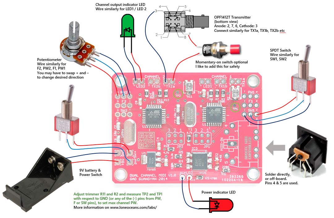
The following are examples of how I assembled one controller together. The controller was assembled using just one of the outputs per channel (the other per channel not connected), with a momentary push-button switch for each channel, and two potentiometers per channel for pulse-width adjustment. The push-button is connected in series with the output to the fiber transmitter, which acts as a safety switch - i.e. the user needs to hold down the button at all times for signal to be sent to the coil.
Note that this uses a slightly earlier prototype version of the board with black soldermask. The new one is slightly smaller and improves on the layout, but functionality remains identical. The compact size of the controller allows for mounting into very small boxes.
Max Pulse-Width Adjustment
There are two small pulse-width adjustment trimmer resistors on the board for each channel, and two tap points (TP1/2). This was designed specifically as a safety feature for your coil to limit the maximum pulse width. This trimmer can be adjusted as a maximum pulse-width limit for your coil-driver system. Pulse-width limits increment in 45us using the equation below. The desired Pulse Width Limit (increments of 45us) can be set by adjusting the potentiometer value using the table below and a voltmeter, and measuring the voltage on the tap point (TP) beside each trimmer resistor.
Just as the the MIDI/fixed modes are read by the microcontroller upon start-up, the max pulse width adjustment is also similarly read at start-up and cannot be changed on the fly. A simple power cycle is required to change the pulse width limit. I recommend verifying the max pulse-width with an oscilloscope after setting.
Max Pulse Width (us) = Floor[(TP_volts+0.04) x 1.59375] x 45us
| Desired Max PW (us) | 10us | 45us | 90us | 135us | 180us | 225us | 270us | 315us | 360us |
| Recommended TP Voltage to set. Exact value not critical. |
0V | 0.90V | 1.53V | 2.16V | 2.80V | 3.43V | 4.06V | 4.70V | 5V |
Testing the Controller
The following steps should get you started with making sure the controller works:
Fixed Mode
In fixed mode, the controller will output a range of pulses with frequency from about 100 to 300 BPS, with a pulse width ranging from 10us, to the max-pulse width configured by the user via the Max-Pulse-Width trimmer. Lets say the user has set TP1 and TP2 to 2.2V for a max PW limit of 135us.
The following table shows how the switches and potentiometers affect operation of the controller:
| Potentiometer / Switch | 0V (-) | 5V (+) |
| Pulse Width Pot | 10us | Max (set by trimmer) |
| Frequency Pot | ~300 Hz | ~100 Hz |
| MIDI / Fixed Switch | Fixed Mode | MIDI Mode |
MIDI Mode
The controller reads the first Channel of each MIDI file and outputs it to Channel 1. Likewise, it reads the 2nd Channel of each MIDI file and outputs it to Channel 2. As a result, MIDI files / MIDI instruments must be configured by the user appropriately to play the correct tunes on the correct channels. The controller ignores all channel events from 3 to 16.
The controller specifically reads the following events during playback:
In the noisy environment of an operating coil, MIDI cables and USB MIDI Cables including power cables can cause MIDI devices to lock up. In such events, it is possible for an incorrect note-off to be sent, or simply not sent to the controller. This may cause the controller to appear 'locked on', whereby the only fix is to send a note off event or a power cycle.
Standard Tesla Coil EMI shielding principles apply!
The controller reads a standard MIDI signal such as from a musical keyboard (which usually outputs only to the first channel - and therefore only to one coil unless a separate MIDI mapper is used - for example some keyboards maybe able to map each alternate key to the first two channels and so on). Another method is to play a MIDI file on the computer and use a simple USB to MIDI cable widely available on Ebay for about $5 each.
For testing with a computer, one free software is the venerable MIDI Editor. Simply load a MIDI file, ensure that the track you wish to play is on Channel 1 or 2, and set the output from the internal synth to USB output (for using with a USB-MIDI cable).
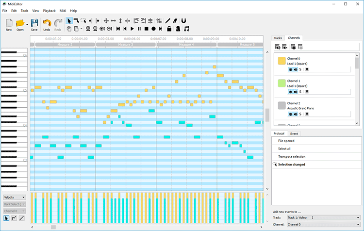
For testing via a computer as a MIDI device, I have prepared a double channel MIDI file: Download here.
The first Channel (Channel 0) plays the melody and the second channel
(Channel 1) plays the harmony of this classical Bach piece. Do not
confuse tracks with channels!
These should
correspond to Channel 1 and Channel 2 of the MIDI controller respectively.
Remember to ensure that the MIDI is set to output correctly (go to Midi >>
Settings >> and check the USB device as MIDI Output) - the controller TX
LEDs
should light up in sync with the flashing LED of the USB-MIDI adaptor as well.
Boards come fully populated and programmed and ready to use. However, controllers can be programmed by the user in the event of future firmware updates, via the AVR ISP header using the AVR ISP ii programmer or similar.
- Programmable via the commonly available AVR ISP mk ii and Atmel Studio 7 or
later (free download from Atmel.com)
- Open Atmel Studio and select Tools > Device Programming
- Ensure that the 6-pin header is plugged in and power applied to the micro
(green light on AVR ISP will turn on)
- Select the Device to be ATmega328P or 328PB, depending on the IC that is
supplied on your board
- When you click Read you should see ~5V as the target voltage
- Ensure ISP clock is at 125kHz
- For Fuses, ensure sure that
> CKDIV8 is not
selected
> SUT_CKSEL is set
to
EXTFSXTAL_16KCK_14CK_4MS1
> Alternatively, program Extended, High and Low
fuses as follows respectively: 0xFF/F7, 0xD9, 0xE7
> (Note that these fuses are FF/F7, D9 and 62 by
default with the 328P ID being 0x1E950F and 328PB ID being 0x1E9516)
- Program fuses, then program desired .hex file in the Memories tab
This is the schematic for the interrupter.
All controllers come with the latest most stable firmware pre-programmed.
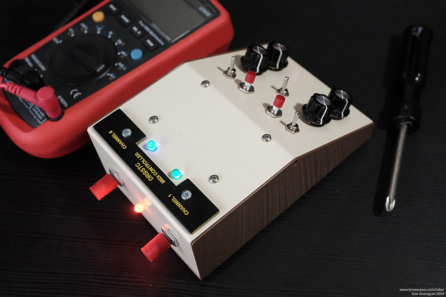
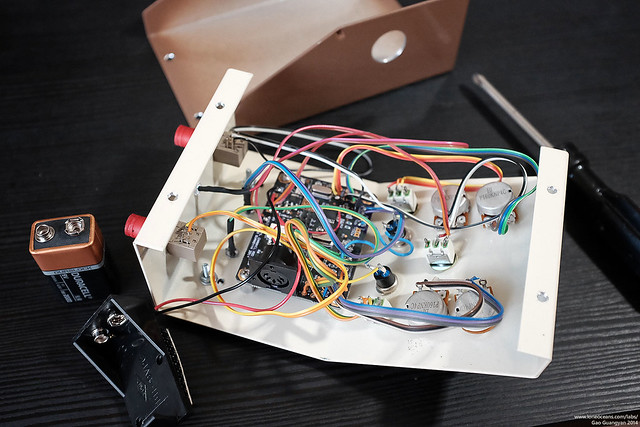
The following is an example of a build from Sam, with photographs reproduced here with his permission. Sam built the MIDI2 controller into a very nice and compact enclosure, and he uses it to control two small SSTCs via fiber optic. Here's what he has to say:
After all the frustration of trying to operate two SSTCs at the same time using one output interrupter with a spilt optical fiber, I come across this controller board by loneoceans! Its high functionality and performance, easy assembly, ease of use, and output to 4 coils at the same time, is all you need for dual channel Tesla-coils. A must have controller board for Tesla coil enthusiasts. I am glad that I actually own one now! It's so much fun playing dual coils with it.
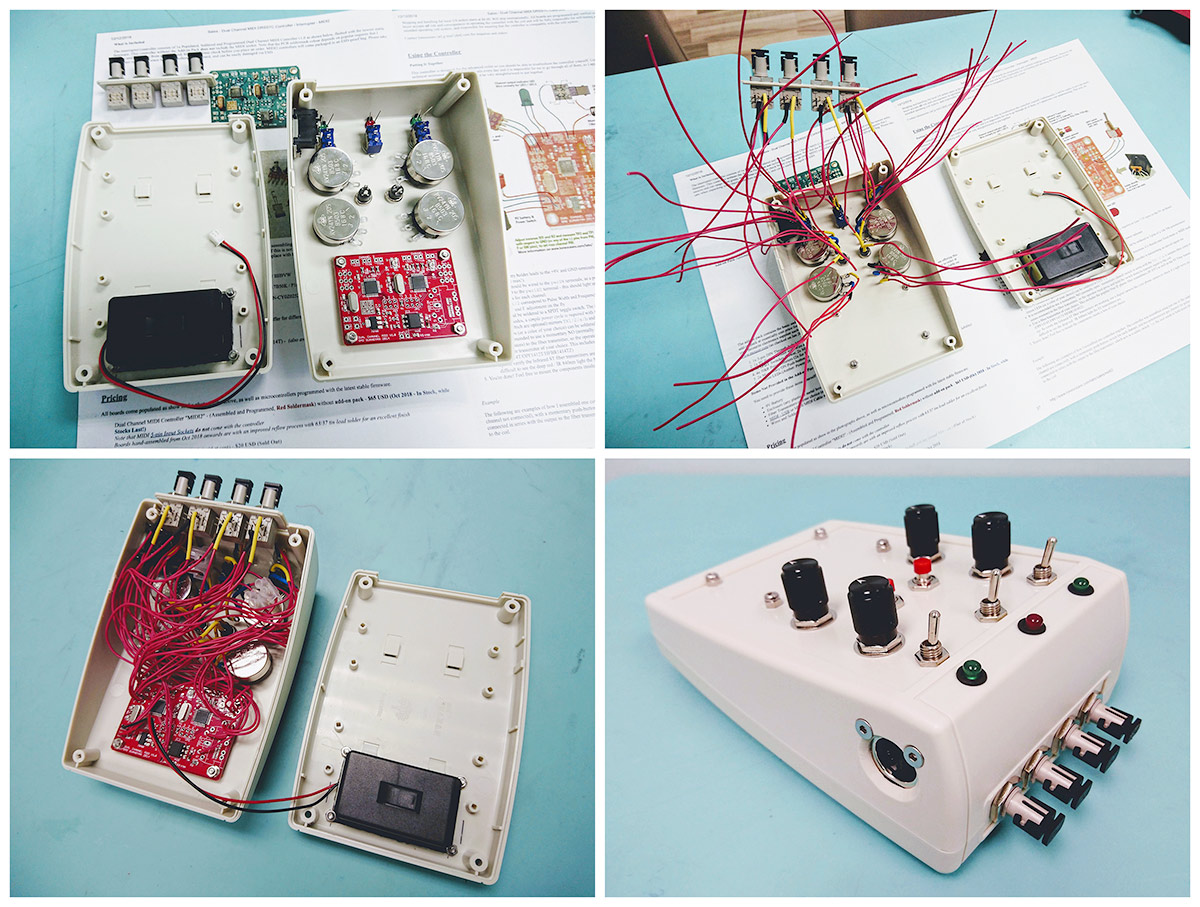
Above are photographs of Sam's build. In his build, Sam used a red LED as a power indicator, and two green LEDs as signal indicators. Four fiber optic transmitters are mounted on the front of the enclosure, and a 5-pin MIDI receptacle is mounted on the right-side. Click to enlarge.
Video of Sam's twin desktop SSTC coils playing music using the MIDI2 controller,
provided by Sam.
Thanks Sam for your kind words, and great job with the excellent build.
Below are coils (both single and double) coils running with this controller:
See www.loneoceans.com/labs/ for more information.
Back to loneoceans labs. (Updated Oct 2020)