|
4" Tesla Coil 2 -
(2004/2005)
Page best
viewed at 1024 x 768 resolution in Microsoft Internet Explorer
|
Index
the 3kW Tesla Coil
 Introduction:
Introduction of this project and overview. Introduction:
Introduction of this project and overview.
Construction:
Day by day construction details.
Testing: Testing,
debugging, improvements and experiments.
Pictures and Videos: Multimedia of the coil in action!
Others: Miscellaneous
Current Project
Status:
Project Completed, Tesla Coil Stable and working!
- 4 MOT Stack
completed and plugged in!
> Including photos and a
video! (27th Jan 05)
Tesla Coil Completed!
(31st October 2004)
Construction Period (25th July 2004)
Just Started (18th July 2004) |
|
Introduction
After the success of my
180W
40mm Tesla Coil, I decided to build a much more powerful
Spark Gap Tesla Coil (SGTC), but not being too big to be
difficult to transport. This page
catalogs the construction and testing of the new Tesla Coil as
well as performance pictures and videos.
My previous Tesla Coil had
a 40mm diameter secondary, and ran at some 180W from a
6kV 30mA Neon Sign Transformer (NST) (Previously a 750W 30mA
unit, but that one died so I had to change a transformer). My previous experience
told me that NSTs were really difficult to find cheaply... at least
in this area... and thus I opted for a Microwave Oven
Transformer Stack to power the new coil. The secondary
diameter was decided to be of a medium 4" diameter and an Asynchronous
Rotary Spark Gap (ARSG) would be built for the new coil.
The 180W Tesla Coil was
built in November 2003, during the school holidays. I decided
instead of concentrating my efforts all into the tesla coil at
one, I would build this slow and steadily. Project
construction will begin on 18th July 2004. There isn't much
time during school term so I'll be working on the tesla coil
only when time permits, a bit at a time.
This page will document my
progress and I will document the whole construction and
debugging process. I'm thankful for the many people and
websites which have helped me in the construction of my first
tesla coil and thus I would like to contribute too. If this
page can help or inspire a single person to build another
tesla coil, it is all worth my effort. |
|
Day by Day Construction Index |
|
Sunday, 18th July 2004
Today marks the start of
the construction of the new Tesla Coil! One of the most
important components would be the Power Supply Unit (PSU). This
calls for a relatively high voltage power supply to charge up
the tank capacitor. As such, a PSU is very important as a
Tesla coil could not run without it. Furthermore, other
components directly, or indirectly are affected by the PSU.
This is why I am building the PSU first.
Power
Supply Unit
The Neon
Sign Transformer is the ideal choice for a power supply. They
are of relatively high voltage (up to 15kV) and the largest I
know of is a 15kV 120mA model (These are extremely rare! I've
only seen it in a catalog, but have never seen it anywhere in
real life or known of anyone who has. More common ones
are 6kV to 15kV at around 30mA). Furthermore, they also have
attractive features such as internal current limiting,
effortless paralleling (for increased current), and comes in many different voltages
and currents. However, for some people (especially for those
on a tight budget like me), NSTs might be very difficult to obtain,
or find cheaply. As
such, an alternative power supply has to be used. Enter the
Microwave Oven Transformer (MOT). These are big transformers
found in Microwave Ovens. These are much easier to find (in
old Microwave Ovens) and are also usually available for free,
or at a very low cost. They also provide lots of power.
However, unlike the NST, they are usually of a low voltage
(typically 2000VAC+) but at a huge current (300-1000mA). 2kV
is too low to reliably fire a spark gap, and the huge current
will overheat most spark gaps. Furthermore, MOTs are not as
well current limited as NSTs and thus may seem undesirable for
Tesla Coil use. But these problems can be solved.
A few
months ago I came across
Greg's Tesla coil page, and
in it was described a dual MOT power supply. I found it to be
quite suitable forthe coil I would be building and thus I have
adapted it for use in my new coil. This circuit uses voltage
doublers to increase the voltage from two MOTs. I
modified it slightly to fit the 240V mains here. Below
is a schematic I've drawn for the new tesla coil dual MOT
power supply.
  Here's
the plan. For the power supply, I have 2 similar MOTs in
parallel from a 240V 15A 50hz outlet. The secondaries are in
series, and both cases are grounded. The operation is rather
simple. On the first half of the AC cycle, Diodes D1 are
forward biased and the doubler capacitors (C2) are charged up.
On the next half of the cycle, the current reverses, and the
diodes are reverse biased, and behave like an open-circuit.
The secondaries of the MOTs are now in series with the charged
capacitors (C2). Thus, the sum of all four potentials is now across the diodes, making a 12kVDC (roughly, depending on MOTs)
pulse up to several hundred milliamps to the tesla coil tank
circuit through the chokes L1. This is a classic voltage doubler circuit. The chokes L1 and bypass
capacitors (C3) form an RC low-pass filter to prevent any RF
feedback from the tesla coil. The final output is in the form
of 12kVDC pulses at 50Hz. Greg has used this circuit without
any filter and smoothing, but with excellent results. All
parts can be found from two old microwave ovens and are are
easy to fit an assemble together. More capacitors (C2) can be
added in series to further limit the current draw. Estimated
output would be around 3kW, 12kV at 250mA - more than enough
power! Here's
the plan. For the power supply, I have 2 similar MOTs in
parallel from a 240V 15A 50hz outlet. The secondaries are in
series, and both cases are grounded. The operation is rather
simple. On the first half of the AC cycle, Diodes D1 are
forward biased and the doubler capacitors (C2) are charged up.
On the next half of the cycle, the current reverses, and the
diodes are reverse biased, and behave like an open-circuit.
The secondaries of the MOTs are now in series with the charged
capacitors (C2). Thus, the sum of all four potentials is now across the diodes, making a 12kVDC (roughly, depending on MOTs)
pulse up to several hundred milliamps to the tesla coil tank
circuit through the chokes L1. This is a classic voltage doubler circuit. The chokes L1 and bypass
capacitors (C3) form an RC low-pass filter to prevent any RF
feedback from the tesla coil. The final output is in the form
of 12kVDC pulses at 50Hz. Greg has used this circuit without
any filter and smoothing, but with excellent results. All
parts can be found from two old microwave ovens and are are
easy to fit an assemble together. More capacitors (C2) can be
added in series to further limit the current draw. Estimated
output would be around 3kW, 12kV at 250mA - more than enough
power!
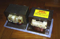
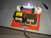
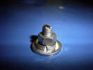
Construction on this power supply began today. I mounted the
two MOTs side by side on a scrap aluminium sheet I had lying
around. The MOTs were then screwed on with self tapping
screws. (see above right) The aluminium base also helps for
easy ground connection as both MOT cores are connected
together. Primary side connections are done. I'll try to fix
up the doubler circuit next week, hopefully if school is not
too busy. As of now, the dual MOT stack weighs 9.5kg and the
cost is $10 (All costs here are in Singapore Dollars; 1.7SGD =
1USD)... bought 2 old microwave ovens from a junk shop. The
aluminium plate is free. |
|
Monday, 19th July 2004
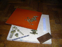
This afternoon after
school, I went to get some components for the power supply.
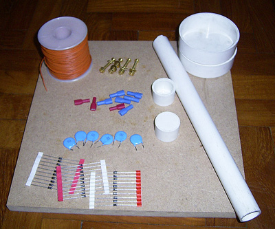
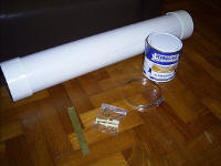
On the left you can see all
the parts.
1 100m reel of cheap PVC
insulated wire (for winding the chokes), $7; 4 5mm brass
screws with 2 nuts and 2 washers each, for connections ($1);
20mm PVC pipe with end caps (for diode stick) and 2 3" PVC end
plugs ($3 total); 6 3kV 0.01uF Ceramic Capacitors (spare), 30
1N4007 Silicon Diodes (15c each, I had some already), and some
spade connectors. Total amount spent today was $12.50, which
makes the total cost $22.50 so far..
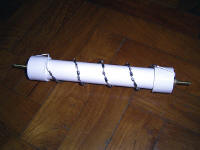
I constructed the diode
stick with the bypass filtering ceramics too. The 6 ceramic
capacitors were soldered in series (giving a 18kV 1.67nF cap,
the values are not calculated, they just seemed like a good
idea..), and were inserted into the PVC tube. 24 1N4007
Silicon Diodes were soldered in series in one long string, and
coiled around the PVC. Electrically, the diodes and caps are
in parallel. The only purpose of the ceramic disk caps is to
allow any RF leakage from the Tesla coil to bypass the diodes,
possibly sparing them from RF destruction. I will begin
building the pancake type chokes soon.
|
|
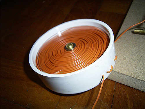
Friday, 23rd July 2004
I had more time to work on
the power supply unit today, and I completed the pancake
chokes. These chokes are used for RF filtering. Instead of
buying power wire-wound resistors, output chokes were wound
instead. I used a similar idea as
Greg's Dual MOT power supply,
and wound my own 'Pancake chokes'. I used 3" PVC end-caps,
which are used to cap off 3" PVC pipes. I drilled holes though
the centres and put a brass machine screw through it. I then
cut out a round plastic piece from 3mm clear acrylic, so that
it just fits inside the end-cap, then drilled a hole through
the centre. I soldered the 5 stranded PVC insulated wire to a
brass nut, and screwed it inside the end-cap. I chucked the
screw into a drill, and spun the wire on, and put everything
together. The wires comes out from a small hole at the side of
the PVC end-cap. It's difficult to really explain the
construction so below is a diagram of how everything goes
together. This results in a nice little package, and the whole
thing weighs slightly more then 200grams. The wire was just
scramble wound onto the brass screw.
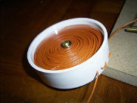
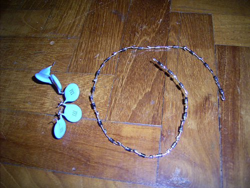
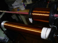
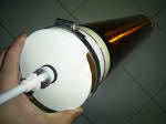
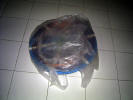
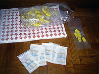
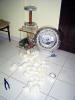
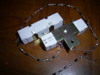
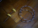
The
first photo is the completed pancake choke. The clear acrylic
allows see-through, and looks nice, however any insulating
material like other plastics would work well too. I happened
to use acrylic since I had some spares left lying around.
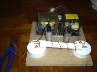
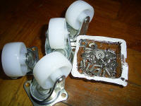
The
second photo is the components of the power supply. There are
2 MOTs, 2 Microwave oven Capacitors (2100VAC, 1uF each), the
diode stick, and the two pancake chokes. The only thing left
is to make the safety gap, and the stick everything down on
that 1/2" thick medium density board, although I might change
to a wooden board because its cheaper :). |
|
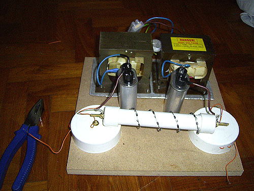
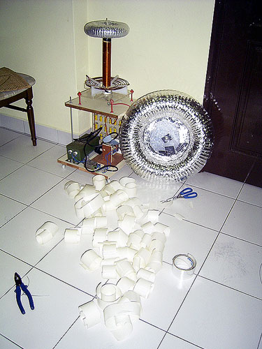
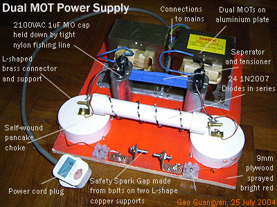
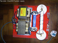
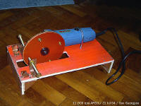
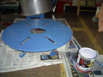
Sunday, 25th July 2004
The power supply is finally
complete! (photo below)
 [On
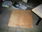
the left is a top view of the setup.] Yesterday, I sawed out a
30.5 x 33 x 0.9 cm plywood board, and sprayed it bright red
(it's fluorescent too), so it was time to finish up the whole
power supply. I bought some #4 1/2" tapping screws (costing
50cents, making the whole cost to be $23). 7 holes (3mm) were
drilled into the aluminum plate (at the sides and corners) and
the dual MOT pack was screwed on to the wooden board. It's
strong enough to hold the 10kgs of MOTs even upside down. A
power cord was then connected to the MOT pack. [On
the left is a top view of the setup.] Yesterday, I sawed out a
30.5 x 33 x 0.9 cm plywood board, and sprayed it bright red
(it's fluorescent too), so it was time to finish up the whole
power supply. I bought some #4 1/2" tapping screws (costing
50cents, making the whole cost to be $23). 7 holes (3mm) were
drilled into the aluminum plate (at the sides and corners) and
the dual MOT pack was screwed on to the wooden board. It's
strong enough to hold the 10kgs of MOTs even upside down. A
power cord was then connected to the MOT pack.
The capacitors are free
standing, but held down by a nylon fishing line (connected to
two screws by the side, like a tent) and the blue piece of
plastic is to separate the capacitors and keep the fishing
line under tension to hold the caps down. This worked rather
well.
 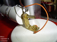 The
diode stick is held above the pancake chokes by two L-shaped
brass supports I cut out from a spare brass sheet. This saves
space too so the footprint of the power supply will not be
that big. See the first picture on the right. The
diode stick is held above the pancake chokes by two L-shaped
brass supports I cut out from a spare brass sheet. This saves
space too so the footprint of the power supply will not be
that big. See the first picture on the right.
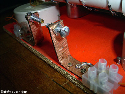
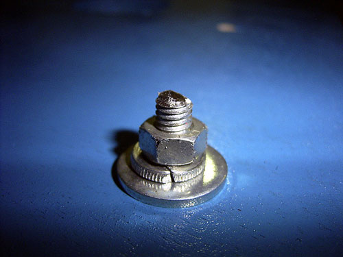
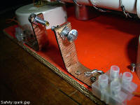
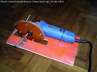
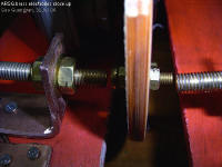
The spark gap (right-most
picture) is made from two L-shaped copper supports cut out
from a spare copper sheet, and two machine screws act as
adjustable electrodes. They are currently galvanized steel,
but I may change them to brass once I buy more of them. The
pancake chokes are not exactly held Down, but are held In
Place by 4 screws screwed down beside them to keep them from
shifting around. (More visible in the top picture of the power
supply unit). The whole setup is quite heavy and weighs
slightly more than 10 kg.
I plugged the power supply
into a 15A 240V outlet.
The voltage multiplier
certainly works. The spark gap is set at almost 10mm, yet it
arcs across. Since the output is pulsed DC, you can
distinctively hear the 50hz pulse from the output arc. The
arcs are similar to that from arcs drawn from a single
un-ballasted MOT, but this time it is much hotter and
brighter, although not as smooth because it is pulsed DC.
After
the completion of the power supply, my next plan is to build
the ARSG, though I need to find a suitable material for the
rotor... |
|
Thursday, 29th July 2004
 I
bought more parts today. I
bought more parts today.
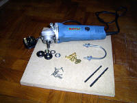
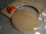
I got a
slightly used (in fact, it looks rather new!) 500W 11,000rpm
angle grinder for only $20. (I have to thank the shopkeeper
for selling it to me so cheap). This would be used in my
Asynchronous Rotary Spark Gap (ARSG). The high speed allows
for very high break rates, but the speed can be controlled with a variac.
I bought
other brass screws, wood screws and also a U bracket and a
bolt for the rest of the project. Since I had some time, I
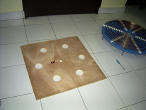
decided to start working on the rotary gap...
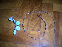
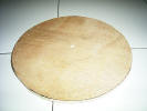
Several
tesla coilers have successfully built the ARSG using an angle
grinder. However, I had difficulties obtaining a suitable
rotor material. Good materials would be FR-4 Fiberglass (G-10 Garolite)
(unclad printed circuit board), Tufnol, phenolic... which have
high tensile strength, and work well under temperature.
However, I couldn't obtain any, so I'm using chopping board
material. I'm not sure what exactly it is, but it's probably
Ultra-High Molecular Weight Polyethylene (UHMW PE). I cut a
13cm dia rotor (small, so there will be less forces), with 4
electrodes (basically 5mm brass bolts and nuts) 2cm from the
edge of the rotor. The center hole is 10mm to fit the arbor.
UHMW PE is easy to work with and I built it in a short time.
However, I ran out of brass bolts so I have to get more. I do
not have much complicated equipment to fabricate the rotor...
I cut out the rotor blank with a jigsaw, marked the centre
holes and electrode holes with a sharp point, and drilled the
holes. I attached the cut out rotor blank and pressed it
against a metal file as it spun. There is no noticeable
vibration at that speed, so I guess it worked. I tested by
screwing two brass bolts (only had 2 left) to test if the UHMW
PE would hold, and it did very well.
However,
there are problems. UHMW PE's working temperature is less than
220F (100C), which is very bad. I am worried that the brass
electrodes would get too hot, soften the plastic and send the
electrodes flying out at high velocities... I'll continue
looking for better materials. |
|
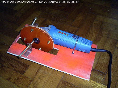
Friday, 30th July 2004
 All
parts for the ARSG have been obtained. All
parts for the ARSG have been obtained.
Many
brass bolts, screws etc have been obtained, costing $10 total.
Brass is not cheap... the M8 x 4" bolts are very expensive at
$2 each. A 8mm drill bit was also bought. I was very lucky and
found a suitable material for the rotor today ($5), making the
total cost $60.50.
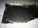
This
material is bakelite (7mm thick). Bakelite, the brand name of
a versatile, heat-resistant resin called
polyoxybenzylmethylenglycolanhydride, and is produced by
combining carbolic acid (or coal tar or phenol) and
formaldehyde. It has excellent insulating and heat-resistant
properties. Bakelite is also known as phenolic, and I have
seen many rotary spark gaps made from this same material.
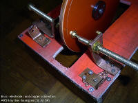
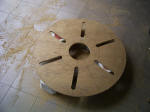
 A
15.5cm diameter disc was cut out using a jigsaw and a 10mm
hole was drilled in the centre (to be attached to the angle
grinder arbor). 4 5mm holes were drilled 2cm from the edges,
and brass screws were used as the electrodes. For the fixed
electrodes, 2 copper L-shaped brackets were made to hold the
adjustable electrodes (in this case, M8 4" brass bolts). They
are so long so I can feed them as they erode away. A
15.5cm diameter disc was cut out using a jigsaw and a 10mm
hole was drilled in the centre (to be attached to the angle
grinder arbor). 4 5mm holes were drilled 2cm from the edges,
and brass screws were used as the electrodes. For the fixed
electrodes, 2 copper L-shaped brackets were made to hold the
adjustable electrodes (in this case, M8 4" brass bolts). They
are so long so I can feed them as they erode away.
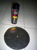
In case
you were wondering, I balanced the rotor but attaching it to
the grinder and spinning it against a coarse grinding stone.
There is no noticeable vibration when this thing is running at
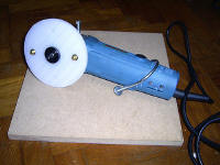
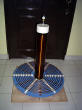
full power so I guess this worked. The
stand is made from plywood (spray painted bright orange to
look better). I cut a slot in the wood to accommodate the
rotor, and the angle grinder is fastened by a U-bolt and
another bolt screwed into the threaded socket on the side of
the grinder head intended for an extra grip handle. This
results in a good 3 point mount. More work will continue on
the stand tomorrow. |
|
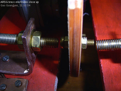
Saturday, 31st July 2004
I decided to complete
the whole ARSG today.
I sawed
out the supports (from plywood) and tap screwed them together.
The electrodes are brass and are screwed on to copper brackets
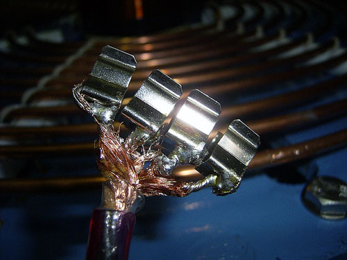
I made from some copper sheet. Multi-stranded copper wire
connects another copper bracket to the main electrode bracket,
whereby the output wires can be screwed onto. The power supply
and ARSG are now completed - 1 step closer to completion! |
|
Friday, 6th August 2004
Due to
the National Day celebrations in school today, we were
dismissed at 10am. I proceeded to acquire more components,
mainly for construction of the secondary coil.
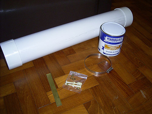
I bought
a 26" long PVC pipe, with an inner diameter of around 4", and
an outer diameter of 110mm, as well as two end caps. ($6.80).
I plan to construct a grounding strip on the secondary, and
the stainless steel ring ($2) would clamp it down. Other parts
include a scrap piece of brass, nylon bolts (there should not
be any conductive parts inside the secondary coil) and other
brass nuts and washers for affixing the secondary to the
platform and the toroid ($2.90), and 1 liter of clear gloss
polyurethane varnish ($11). $22.7 spent. This brings the total
amount to $83.20...
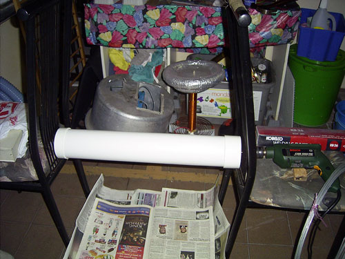
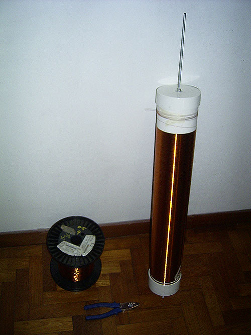
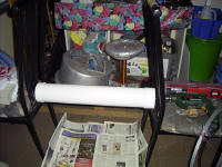
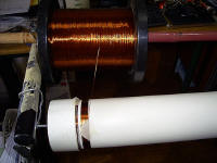
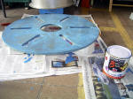
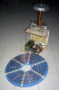
Today I
gave the secondary a coat of varnish. As you can see, I
connected a drill to the coil form, and spun the pipe as I
applied the varnish. It's a crude setup, but just works. The
speed of the drill is varied by a variac. I need to make a
better setup however.
For the
wire, I plan to use 0.5mm wire (AWG 24), wound for 55cm,
making 1100 turns. However, I have yet to find a source of r
the wire... Anyway, the polyurethane takes 24 hours to dry
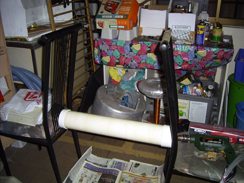
completely. |
|
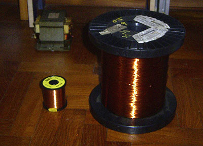
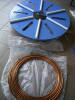
Saturday, 14th August 2004
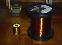 Last
Saturday (7th Aug), I located a good source for the magnet
wire. Look at the photo on the left. Notice a small reel of
wire, a large reel of wire and a Microwave Oven Transformer.
For my
Tesla Coil 1, I used 0.2mm
wire, bought from RS for $31.10 (about 18USD) per 500g
(about 1600m) - quite expensive. I decided to try my luck on
yellow pages and search for motor rewind companies. I found a
small shop in some industrial area, and they indeed had cheap
magnet wire. Last
Saturday (7th Aug), I located a good source for the magnet
wire. Look at the photo on the left. Notice a small reel of
wire, a large reel of wire and a Microwave Oven Transformer.
For my
Tesla Coil 1, I used 0.2mm
wire, bought from RS for $31.10 (about 18USD) per 500g
(about 1600m) - quite expensive. I decided to try my luck on
yellow pages and search for motor rewind companies. I found a
small shop in some industrial area, and they indeed had cheap
magnet wire.
I
bought a half used reel of 0.5mm wire (smallest reel they
had.. new reels are 10kg). This reel contained 3.8kg of 0.5mm
wire! Since my secondary is 110mm dia, I would need around
350m (around 1000 turns) of wire, which means I only need
around 600+g of wire. 3.8kg is enough to wind 6 coils.
However, I did get the wire cheaply, at only $10 (around
$5.80USD) per kg. I paid $38 for the whole reel. Should I have
bought from RS, things would be different. RS sells the wire
at $25.90 for 250m, which means I would have spent $36.26 for
the wire I need. Saved $30! I will definitely go back to motor
rewind shops to buy wire. About $6 of wire was used (to be
counted in the cost for this project).
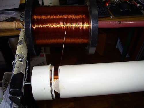
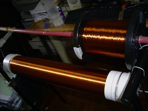
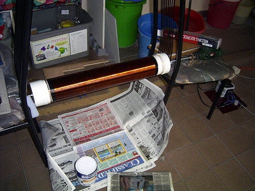
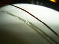
Lets
move to the secondary now. I made a mistake in putting too
much varnish over it. Even after 1 week, it had to dried fully
and there were many blobs all around. This made the whole pipe
useless. I went out the the nearby shop and got another 27" of
4" pipe. After sanding to remove all marks, washing it, and
drying it under the hot sun, I started winding the coil.
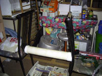
I used
the same winding technique as for my previous coil which used
0.2mm wire. This is a 'poor man's winding jig'! The wire reel
and secondary is placed between two chairs, and everything is
slowly wound entirely by hand. This coil too around 1 and a
half hours of boring winding to complete. Notice how nice and
tight the turns are - it looks like a copper tube! I wound for
55cm length. There should be around 1000+ turns of 0.5 wire. I
hooked it up to my drill with a variac, and spun it slowly as
I applied a THIN coat (learnt from previous mistake) of clear
gloss polyurethane varnish, and let it spin for another 45
mins until the varnish was tacky and could not drip. Upon
close inspection, I realized that a lot of bristles from the
varnish brush had came off and were stuck on the secondary.
Using a thin wire, I painstakingly picked out the bristles,
wasting another half an hour of my time. Next time I'll
probably use a small paint roller instead... also, I need to
redesign the spinning mechanism. At such slow speeds, the
drill is very unstable, and stalls easily. Spin too fast and
all the varnish files off. Anyway, the coil is looking great
and shiny :-). |
|
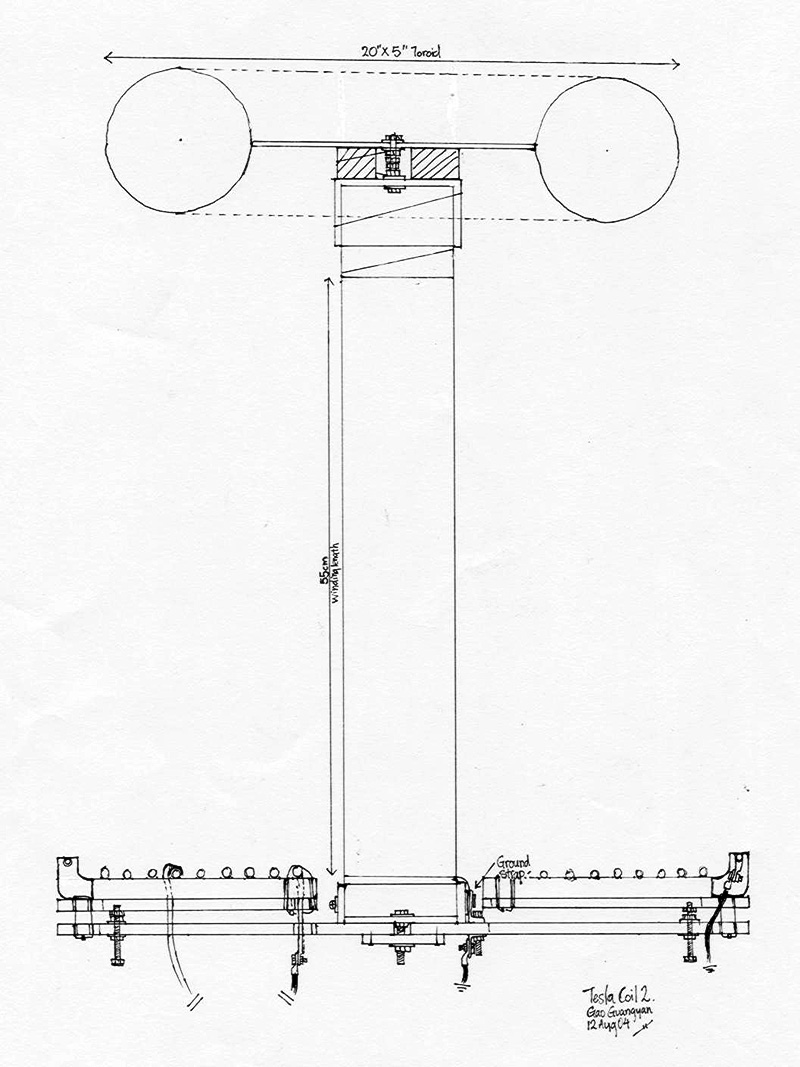
Saturday, 21st August 2004
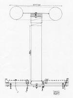 On
the left is a simple to-scale drawing of the primary supports,
the secondary and the top load. On
the left is a simple to-scale drawing of the primary supports,
the secondary and the top load.

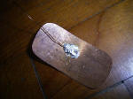
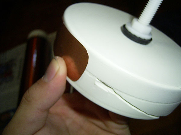
 I
completed the secondary section today. Since the windings and
the coats of polyurethane were done, I proceeded to make the
secondary ground. A rectangular section of an end cap was
marked out and scored with a penknife. A grove was cut using a
Dremel rotary tool and a cutting disc for the wire. A
rectangular sheet of copper was then cut out. The base wire of
the secondary coil was then hammered flat using a hammer
(copper is soft; insulation scrapped off first), and it was
soldered to the copper sheet. The ground sheet was then
epoxied in place. This grounding terminal is very effective. A
grounding strap can be strapped to this copper terminal, and
is easy to attach or remove. 2 long M10 plastic bolts were
screwed in the end caps, and both end caps were epoxied on the
pipe. The large plastics bolts are much better as they are
much larger. Both of them cost $2 together. To see how this
will be attached, look at the drawing above. It's difficult to
explain how it will all fit together. As the project goes
along, you'll see how everything will be fixed together. The
primary is meant to be adjustable too so I can change the coupling. I
completed the secondary section today. Since the windings and
the coats of polyurethane were done, I proceeded to make the
secondary ground. A rectangular section of an end cap was
marked out and scored with a penknife. A grove was cut using a
Dremel rotary tool and a cutting disc for the wire. A
rectangular sheet of copper was then cut out. The base wire of
the secondary coil was then hammered flat using a hammer
(copper is soft; insulation scrapped off first), and it was
soldered to the copper sheet. The ground sheet was then
epoxied in place. This grounding terminal is very effective. A
grounding strap can be strapped to this copper terminal, and
is easy to attach or remove. 2 long M10 plastic bolts were
screwed in the end caps, and both end caps were epoxied on the
pipe. The large plastics bolts are much better as they are
much larger. Both of them cost $2 together. To see how this
will be attached, look at the drawing above. It's difficult to
explain how it will all fit together. As the project goes
along, you'll see how everything will be fixed together. The
primary is meant to be adjustable too so I can change the coupling.
Total
cost of the project is now S$91.20. |
|
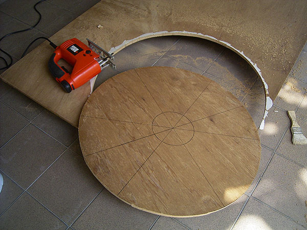
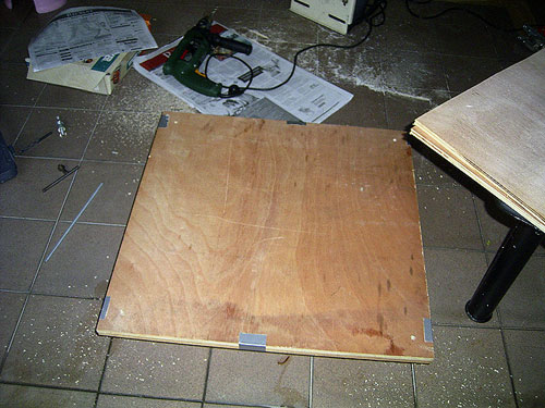
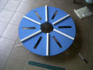
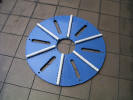
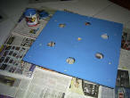
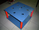
Tuesday, 7th September 2004
Due to
school being irritatingly busy and stressful, it was difficult
to find time to work on the tesla coil, until now. It's a 1
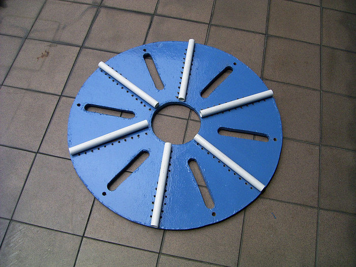
week school September holidays. I decided to start making the
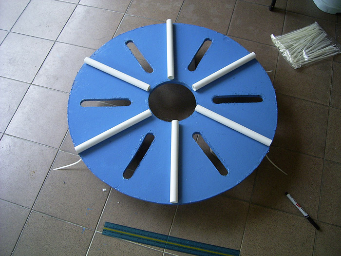
adjustable primary supports. A 2 foot diameter circle was cut
from 1/2" plywood using a jigsaw. (I got the wood free
from some construction site nearby which junked lots of wooden
boards) A hole was cut in the middle
of the circle (where the secondary will be) and 6 slots were
cut for easy tapping of the primary from below. 1 litre of
Nippon Bodelac Wood/Metal paint and a brush was bought ($14).
I choose Blue Marines because it seemed to be the best colour.
The primary deck was given two coats of paint. The result is
rather nice. I'll be buying 50' of copper tubing tomorrow
(hopefully) and then construction of the primary coil can
commence!
Total
cost of the project is now $105.20 |
|
Wednesday, 8th September
2004
  Several
more parts were bought today. Several
more parts were bought today.
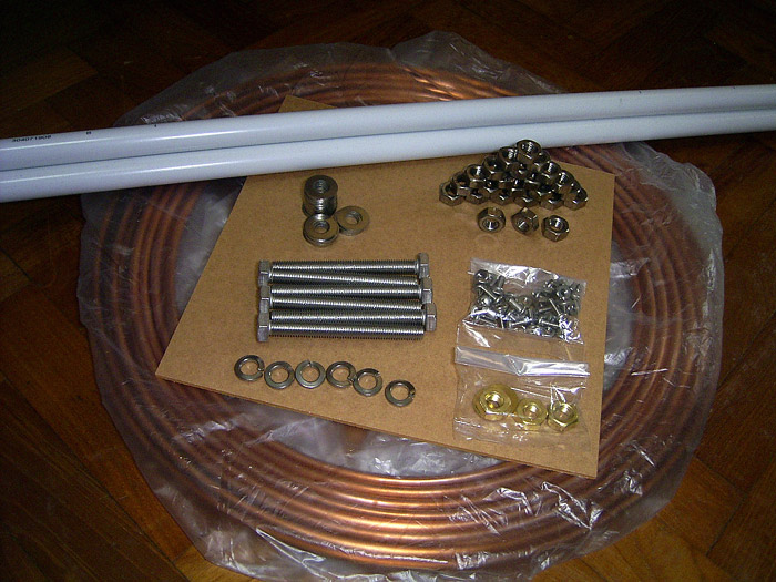
50 Feet
of 1/4" Flexible Copper Tubing for the primary coil ($20), 3
metres worth of 3/4" PVC pipe for the primary supports (3
metres was the shortest length they have, but it's cheap for
only $1), and many bolts and accessories - 6 big M10 Stainless
Steel bolts for the adjustable primary, along with many nuts,
washers and lock washers; 20 smaller stainless steel bolts for
wire connections and M10 brass nuts and washers for the
secondary top attachment to the toriod. I probably bought too
many, but these can be used next time for other projects. The
stainless steel stuff are not cheap, total cost being $16.
Since the primary deck paint was still wet at the edges (due
to an unskillful application of too thick a layer of
paint...), construction is delayed. I cut a grove at the
top of the secondary for the wire to wind up to the topload.
Everything is looking okay, but progress is painfully slow.
Total
cost of the project is now S$142.20 |
|
Thursday, 9th September
2004
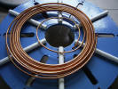
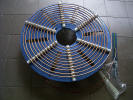
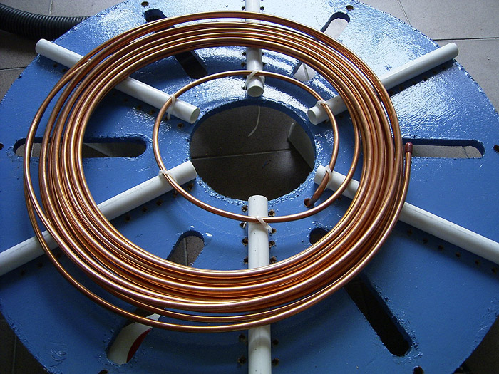
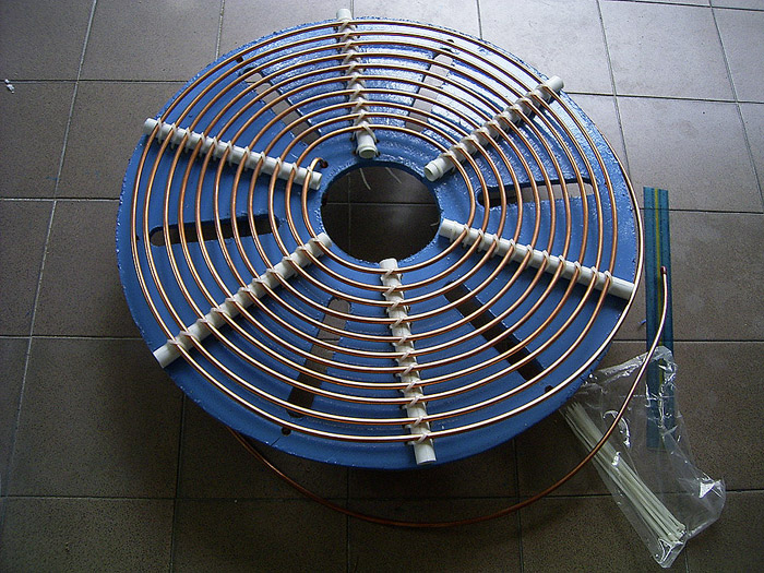
Today I
completed the primary coil. It has slightly less than 10.5
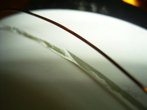
turns, and is made of 1/4 inch diameter soft copper tubing
wound in a flat spiral, with 1/2 inch separating each turn. The insulating supports are 23.5cm
pieces of 3/4" PVC pipes. They are tied down at the ends by
cable ties. (photo 1). In photo 2, you can see the lovely 50
foot roll of copper tubing. Around 120+ 5mm dia holes were
then drilled beside the PVC supports (not very well done by it
works..). The cable ties go through the holes, over the copper
tubing (which rests on the PVC supports) and back down through
the other hole and firmly clasps the tubing to the primary
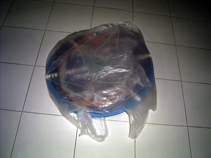
deck. (Photo 4 and 5). The coil is held in place by over 60
cable ties. I might even use 1 more per support to make it
even stronger. Compare the size of it with my mini 40mm 180W tesla coil (photo 6). The finished coil is kept in a plastic
bag to protect the copper from oxidising.
This is
an extremely simple method for winding a flat primary, and
yields a very sturdy finished product. I thought it might look
quite messy, but it's actually quite neat. It requires no
complicated machining, notching or precision work. Only common
hand tools were used to make it... a drill, a ruler and a
marker. The main drawback is that it is rather time consuming.
I took around 2 - 3 hours to complete the primary. Although
easy, it was very tedious lacing and clinching the many cable
ties. Many people report all sorts of nightmarish tales of
primary construction, including turns that come loose and
don't stay, plastics that are impossible to glue, difficult to
cut precisely etc.. This is very different with this method.
Easy, but tedious and rather boring.
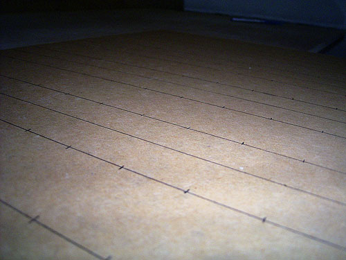
Here's how I marked out the
pipes for the copper tubing.
Although
the top looks relatively nice, the bottom is chaos. There are
many things that can be learnt. Firstly, cheap plywood is
lousy to work with. Everyone knows that when you drill plywood
fast, the bottom ply tends to crack off. This is exactly what
happened in this and the whole bottom looks like cracked wood.
I'm not so concerned about it because it will be covered by
another deck which this primary deck is resting on, but it
still looks ugly. Secondly, don't apply too thick a coat of
paint and make sure it doesn't form drips or blobs because it
takes an exceedingly long time to dry. Next time, if I make
something like this, I'll probably be using PVC sheets all the
way. For now, I'll still stick to wood and paint. In any case,
I still got the wood free, and I don't want to waste the
paint.
This
primary coil design is by Greg Hunter, who uses it on his 4"
Junk box coil and 6" coil.
http://www.hot-streamer.com/greg/.
Credit must go to him for such a innovative and good design. |
|
Saturday, 24th October 2004
 School
has been *extremely* busy, so I had no time to work on this
coil at all. However, the end-of-year examinations are just
over, and the holidays are coming, so I will be able to resume
work soon, and hopefully complete the coil in early November. School
has been *extremely* busy, so I had no time to work on this
coil at all. However, the end-of-year examinations are just
over, and the holidays are coming, so I will be able to resume
work soon, and hopefully complete the coil in early November.
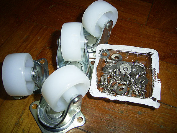
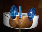
I went
out the the shop and got some 1.5" Nylon wheels and some
stainless steel Pan Self Tapping Screws and washers to attach
the wheels (base will be wood). Total cost is S$12.80 bringing
the project cost to S$155.00. I was planning to cut the wood
to make the box to house everything, but to my horror, the
plywood I had was either too small or was disintegrating. This
made me unable to carry on building. I shall buy some new
wooden boards sometime this week.
The coil
is actually mostly complete. I need to build the toroid (5x20"
out of PVC ducting covered in aluminium tape), the capacitor
bank (will be using a MMC, though the caps won't be cheap),
the frame to hold everything together, the wiring, safety
circuit and finally to paint it. I expect to complete it in
two weeks if everything goes well. I shall order the MMC
capacitors soon. |
|
Thursday, 28th October 2004
Yesterday was the last day
of school. It's the November/December Holidays. I went out and
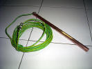
got everything else I needed to get for my tesla coil.
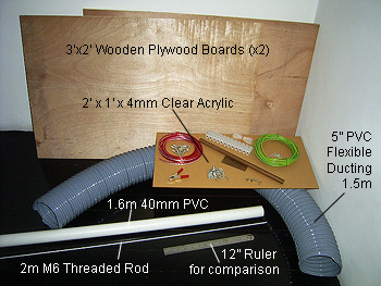
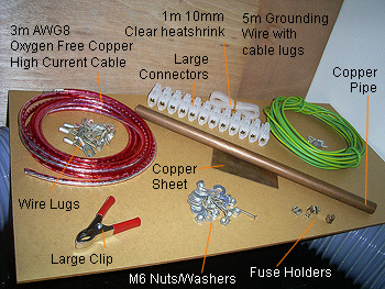
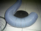
Refer to
the above photos. The two 3' x 2' x 11mm Plywood boards ($6
each) for the box to hold everything together. Supports will
be made out of the 40mm PVC pipe ($2.50) and held together by
the threaded rods ($2 for 2m, will be cut). The Toroid will be
made out of the 5" Inner Diameter PVC flexible ducting ($24
for 1.5m). The 2' x 1' x 4mm Clear acrylic (covered with brown
paper to protect) ($10) is for the capacitor bank. For the
primary wiring, I will be using AWG8 Ed Acoustic Super Oxygen
Free Copper Interconnect High Current Cable ($7.50 for
3m), with the suitable cable lugs ($4 for 16) and clear
heat-shrink ($2) to keep it nice. For the primary tapping, I
will be using either the large crocodile clip (90c) or the
fuse holders (60c). For connections, I will be using either
the wire lugs or the large industrial sized (these are huge
compared to the 15A ones for normal use!) connectors ($0.70).
The grounding rod will be the copper pipe ($2) and will be
connected to the Tesla Coil via a 5m long wire (the green and
yellow one) ($4.80 with lugs). The copper sheet is for other
misc connections. Finally the frame will be held together with
the M6 Nuts, washers and lock washers and others ($1.50).
The
capacitors and resistors have also arrived!
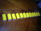
The
capacitors and the yellow one. I bought 65 of them These are
0.1uF 1500V Axial Polypropylene capacitors from RS Singapore.
I quote from their catalog, "Film-foil polypropylene
capacitors protected by polyester wrap and epoxy end seals.
With very low loss dielectric suitable for continuous use a
high ac voltages. It will withstand fast rise time pulses and
has an excellent high frequency performance." Each capacitor
costs $3.42, stock no. 114-480. I will be wiring 5 strings of
12 capacitors yielding a capacitor bank of 41.7nF rated at
18kV. Total cost is $222.30
For the
resistors, I bought 60 of them, each costing $0.30, costing
$18 in total. The resistors are 0.5W 10MegaOhm each. I quote
from the catalog "The VR series of resistors comprise of a
metal glazed film deposited on a high grade ceramic former
with end caps and welded tinned electrolytic copper
termination wires. The body is protected with a light blue
insulating lacquer. These resistors are for applications in
which high resistance, high stability and reliability are
required at high voltages. The resistors meet the safety
requirements of IEC65." Although the total cost is $240.30, I
managed to get a discount and got the resistors and caps for
$214.99 instead.
Total
amount spent today: $70.50 + $214.99 = $285.49, making the
total project cost (as of now) to S$440.49! An expensive day.
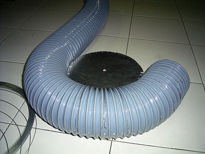
I decided to build the
toroid today. A nice toroid is important, but a professional
spun aluminium toroid would be very expensive (few hundred).
As such, I decided to make my own 5" x 20" (turned out
slightly bigger) toroid. Building my own toroid cost around
$30 and about 3+ hours of work. The method I used was from
Easternvoltageresearch's page, which can be found
here.

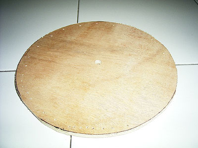
First, a 10 inch dia centre
disc was cut out from 9mm plywood using a jigsaw. (picture 1)
I drilled holes around the edge at roughly 1 inch intervals. I
drilled more holes where the PVC ducting connects to have a
stronger joint, as it will need more support. Notice the
centre hole. This is drilled to accept a M10 plastic bolt from
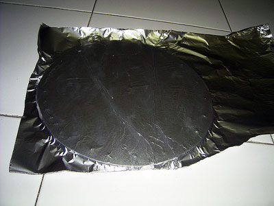
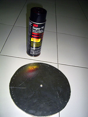
the top of the secondary coil. I sprayed the disc with 3M
Super 77 Spray Adhesive and stuck aluminium foil on it (photos
2, 3), and cut out the excess foil with a penknife. The PVC
ducting was then attached using wire. The wire goes through
the hole in the plywood, around the ducting, and is twisted
with pliers (photo 4). Twisting will fasten the ducting
securely to the centre disc. Bend the twisted wire into the
groove of the ducting. This part was the most difficult
especially at the part where the PVC ducting comes together.
More wire does it. Photo 5 shows the completed toroid without
its aluminium covering. After that, I used 2" wide aluminum
tape and taped up the whole toroid. The last photo shows the
result compared with my 40mm mini Tesla coil.
Let me
tell you a story about the aluminum tape I used. I first
bought this tape before building the toroid of my
1st
tesla coil. I didn't know where to get tape like
this back then. One day, when I was at a shopping centre with
my mum, I saw this tape at a home-fix shop, and promptly
bought it. It was $15, but I couldn't wait. Anyway, few days
after that, I went looking for more parts at the industrial
area, and found shops selling the tape for $6 only - wasted
$9. What is the moral of the story? The moral of the
story is that we should never buy stuff like this from the
shopping area as we will most definitely get ripped-off.
Anyway, I was surprised that the tape managed to last for so
long - two smaller toroids and this big toroid. Anyway, the
toroid is looking good. To be fair, I will add $10 to the
project cost as I estimate I used about 2/3 of the $15 tape.
Project
cost is now: S$450.49! I will continue work tomorrow. |
|
Friday, 29th October 2004
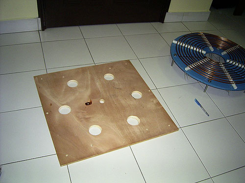
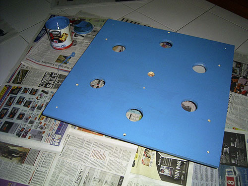
I did lots of machine work
today.
I cut
out two 2' squares from the 11mm thick plywood I bought
yesterday using a jigsaw (photo1) and drilled appropriate
holes for the supports (threaded rod). Here's how the primary,
secondary and top board looks like now (photo 2). The primary
deck will be adjustable. I subsequently drilled 6 larger holes
on the top deck for primary tapping (photo 3). I finished the
boards with a coat of Nippon Bodelac Wood/Metal paint, and
left it to dry overnight. I will paint the other side
tomorrow.
I also
started work on the capacitor bank. The capacitor bank is an
essential part of a Tesla coil. It had to be able to withstand
repeated charging and discharging and the oscillations of the
tank circuit. Furthermore, the radio frequency places enormous
stress on the capacitors. Professional pulse capacitors needed
for Tesla Coil like the one I'm building will easily cost
several hundreds or even thousands of dollars. I have opted to
use a MMC (Multi-mini capacitor) bank. This is basically
several small professional pulse capacitors wired up in
series/parallel. The capacitors arrived yesterday.

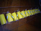

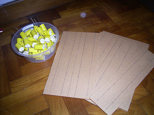
I marked
out the acrylic board (photo1), drilled 120 holes and cut it
using a jigsaw (photo 2). The capacitors are slotted in and
are wired in series (twisting the leads) (photo3). The
resistors are added for charge equalization and for safety
(photo 4), and everything is soldered together (photo 5). The
is one string of 12 capacitors. I have 4 more to, but I'll do
them tomorrow. It's getting late.
I will
complete the painting tomorrow morning, finish up the
structure in the afternoon, complete the capacitor bank and
wire everything up by night. I should be able to get it fired
up on Sunday! |
|
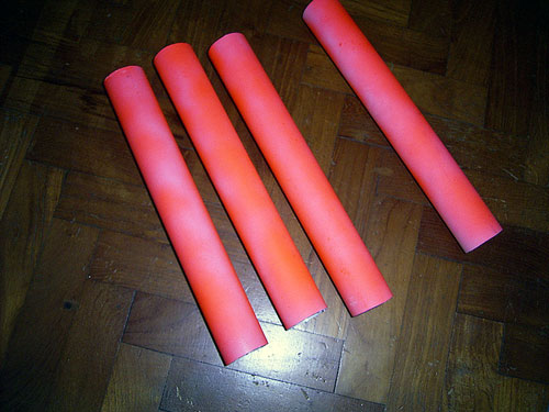
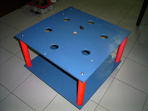
Saturday, 30th October 2004


  I
built most of the frame today. The paint had dried already, so
I screwed the four nylon wheels on the bottom frame with 16
stainless steel pan screws. (photo 1). I sat on them (around
55kg) and it rolled easily, so it can definitely support the
whole Tesla Coil. I also cut out 4 30cm 40mm PVC pipes (photo
2) as supports, and sprayed them florescent orange (photo 3).
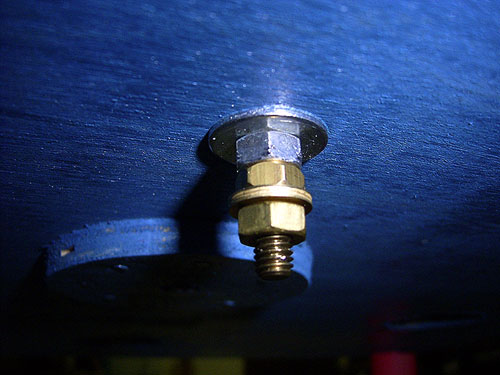
The two boards are screwed together by 4 long threaded rods
(photo 4). The complete frame can be seen in photo 5. The
photo on the left shows the ground connection under the top
deck. If you look closely at photo 5, you will be able to see
a L-shaped copper bracket which is connected to the bottom of
the secondary coil. The ground wire is screwed here.
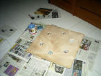
Everything is looking good. The photo above right shows a mock
setup with the adjustable primary deck, secondary, toroid,
spark gap and power supply. However, due to the busy schedule
today, I didn't manage to do much. The coil is almost
complete, more work will continue tomorrow and I hope to fire
it up tomorrow night! I
built most of the frame today. The paint had dried already, so
I screwed the four nylon wheels on the bottom frame with 16
stainless steel pan screws. (photo 1). I sat on them (around
55kg) and it rolled easily, so it can definitely support the
whole Tesla Coil. I also cut out 4 30cm 40mm PVC pipes (photo
2) as supports, and sprayed them florescent orange (photo 3).
The two boards are screwed together by 4 long threaded rods
(photo 4). The complete frame can be seen in photo 5. The
photo on the left shows the ground connection under the top
deck. If you look closely at photo 5, you will be able to see
a L-shaped copper bracket which is connected to the bottom of
the secondary coil. The ground wire is screwed here.
Everything is looking good. The photo above right shows a mock
setup with the adjustable primary deck, secondary, toroid,
spark gap and power supply. However, due to the busy schedule
today, I didn't manage to do much. The coil is almost
complete, more work will continue tomorrow and I hope to fire
it up tomorrow night! |
|
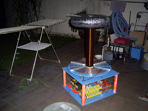
Sunday, 31st October 2004
I did the final bits of
work today.
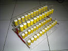


Take a
look at the 60 capacitor MMC bank! (photo 1). 5 strings of 12
capacitors, making a 41.7nF 18kV capacitor bank. Everything is
mounted on 4mm clear acrylic. Primary connections are 3 thick
copper wires with output lugs. I think it looks rather good
:-). The second photo shows the copper ground rod which will
be pounded in the earth. It has a 5m wire attached to it.
photo 3 shows the primary tap I made out of 4 fuse holders.
There is a lot of surface area, and is easy to tap. All
primary wiring is done by 8AWG Oxygen Free Copper high current
audio cable. Luckily I had foresight and bought a large 60W
soldering iron, otherwise it would be almost impossible to
solder the thick wires of the capacitor bank and the fuse
holders etc. I completed everything, and the last photo shows
the coil in my backyard. I have to run this thing off 2 mains
outlets. One 15A 240V one for the dual MOT power supply, and a
13A 240V outlet for the 500W angle grinder (spark gap).
Construction is finally complete! |
|
--- 31st
October 2004, Construction is Complete! --- |
|
Testing, Experiments,
Etc. |
|
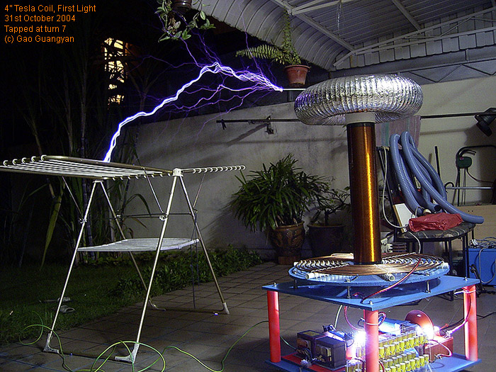
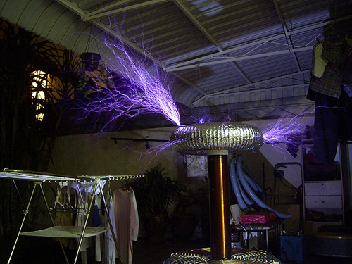
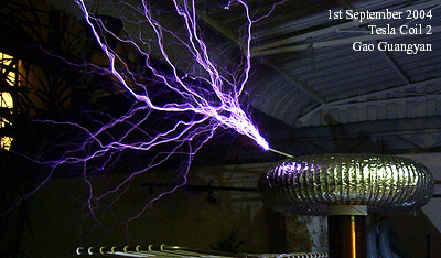
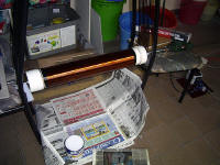
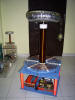
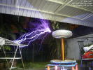
Sunday, 31st October 2004
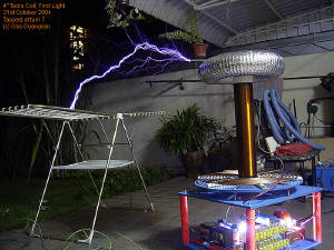 *First
Light* *First
Light*
I
completed the coil today, so I plugged it in and fired it up.
The secondary ground is connected to a 50cm long copper rod
pounded in my garden (the yellow/green wire). I used two mains
outlets to power it: a 13A 240V outlet for the 500W ARSG, and
a 15A 240V outlet for the main power supply. I'm still not
sure how much power it is drawing, but I will do measurements
soon. It was getting late so I lashed it up quick, placed a
metal rod on the toroid, shifted the clothes hanger nearby,
and tapped the primary at turn 7. The ARSG was set at full
power.
I turned
on the power and the whole coil roared and erupted with
streamers! I turned off the power, set up my camera, and
proceeded to take the photo you see on the left. However, the
fun ended when my dad came and told me to continue tomorrow...
it was so noisy. (I was wearing ear muffs so it wasn't that
loud to me :P ). Arcs are really thick and scary. I didn't
measure the arc length but I estimate the arc length in the
photo to be roughly 90cm long. Notice how bright the main gap
is. You can also see the safety gap firing. I will be tuning
it tomorrow night and I hope to get better performance.
Everything is looking very good. I can't wait to fire it up
again tomorrow! |
|
Monday, 1st November 2004
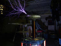

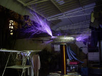
 The
second run! Alas a few seconds after turning on the power, the
coil suddenly stopped. I did a quick check and everything
seemed to be okay. I disconnected the power supply from the
primary circuit and turned it on. The MOTs buzzed and nothing
happened, no arcing at the electrodes. As I went to check the
power supply, my hand brushed against the 24 1N4007 string. It
was then that I realised that the diodes were *very* hot.
Since everything else seemed ok, I got two Microwave Oven
Diodes in series and replaced the diode string... and it
worked. However, the big diodes are still getting hot,
limiting the runs to only a few seconds at a time. Anyway, it
was getting rather late again and my dad told me to keep the
stuff and do it again tomorrow (earlier), so I haven't really
done much at all. I did try the primary taps though. At turn
8, there is hardly any spark output. Turn 6 is similar to turn
7 but I'm not very sure yet. I took 3 photos of the coil in
action. Meanwhile, I will try to find out the problem of the
diodes. The MOT caps remain cool.. only the diodes get very
hot. The
second run! Alas a few seconds after turning on the power, the
coil suddenly stopped. I did a quick check and everything
seemed to be okay. I disconnected the power supply from the
primary circuit and turned it on. The MOTs buzzed and nothing
happened, no arcing at the electrodes. As I went to check the
power supply, my hand brushed against the 24 1N4007 string. It
was then that I realised that the diodes were *very* hot.
Since everything else seemed ok, I got two Microwave Oven
Diodes in series and replaced the diode string... and it
worked. However, the big diodes are still getting hot,
limiting the runs to only a few seconds at a time. Anyway, it
was getting rather late again and my dad told me to keep the
stuff and do it again tomorrow (earlier), so I haven't really
done much at all. I did try the primary taps though. At turn
8, there is hardly any spark output. Turn 6 is similar to turn
7 but I'm not very sure yet. I took 3 photos of the coil in
action. Meanwhile, I will try to find out the problem of the
diodes. The MOT caps remain cool.. only the diodes get very
hot. |
|
Tuesday, 2nd November 2004
I think that the filter
chokes are actually doing more harm than good. Some
detrimental oscillations could have been created which could
have blown the diodes. Today I removed the chokes and tested
the coil again. The coil worked for around 2 seconds, and
stopped. The microwave oven diodes are hot and they probably
died too. I'm not sure if they died because of the removal of
the chokes. However, the MO diodes were running with the
chokes last night so maybe that might have destroyed the
diodes already. I will be getting some resistors (around 50W
100ohm resistors), and get more 1N4007 diodes and see how they
perform. I can't do anything with the power supply blown. |
|
Wednesday, 3rd November 2004
I bought
some new stuff for around $10 (left). I replaced the diodes
with 24 new 1N4007s and the chokes with 100ohm 30W ceramic
resistors. I ran the coil for a few seconds, and everything
was fine. The resistors got slightly warm and the diodes were
not hot at all.
I ran it again, but suddenly, it stopped. This time the diodes
were hot. I guess the diodes died again.
I can't
get the coil running without the power supply...
However, I have some ideas. Firstly, I realised my safety gap
is too small. I set it small enough for it to arc across when
power turned on so it shorts the supply. Also, there is no 3rd
electrode to ground in the safety spark gap which might also
be a problem. 100 Ohms might be also a bit too little.
Anyway I
will be going for a holiday (school trip) so I'll fix this
when I return. |
|
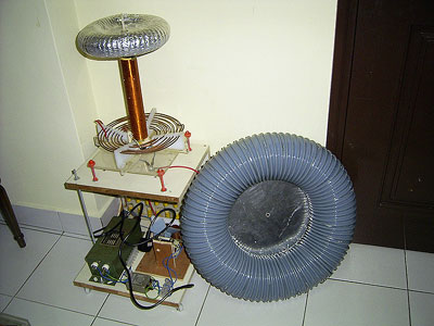
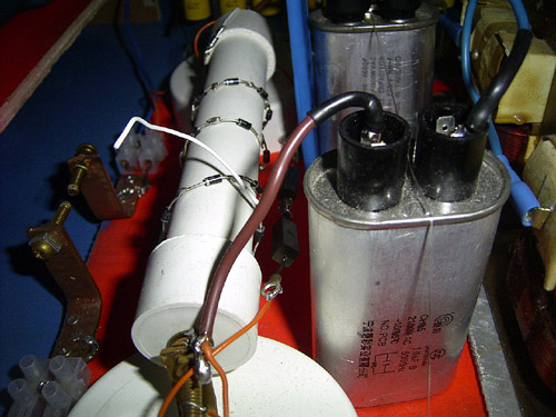
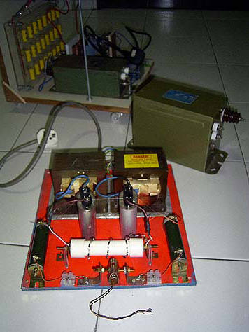
Wednesday, 1st December 2004
 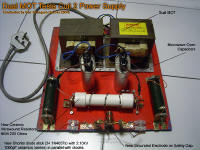 I
bought new components (diodes and resistors for $15.50) and
fixed up the power supply today. Click on the thumbnails on
the left for a larger photo with description. The left most
picture shows the fixed power supply (11kg) and other things.
I got a working 15kV 30mA old Neon Sign Transformer (12kg)
free today from an Neon shop. Need to find a use for it. The
thing in the background is the bottom of my 180W Tesla Coil 1. I
bought new components (diodes and resistors for $15.50) and
fixed up the power supply today. Click on the thumbnails on
the left for a larger photo with description. The left most
picture shows the fixed power supply (11kg) and other things.
I got a working 15kV 30mA old Neon Sign Transformer (12kg)
free today from an Neon shop. Need to find a use for it. The
thing in the background is the bottom of my 180W Tesla Coil 1.
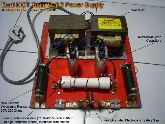
 Anyway,
here's what I fixed.... I replaced the burnt diodes with
another new set of 24 1N4007s; removed the previous 30W 100
Ohm resistors and replacing them with 60W 220 Ohm ceramic wire
wound resistors; Added a new electrode from a squashed copper
pipe which will be connected to RF Ground; shortened the diode
PVC tube; and replaced the older ceramics with 2 new 10kV
1000pF (1nF) ceramics in series. (Yellow ceramics in the photo
on the right). Anyway,
here's what I fixed.... I replaced the burnt diodes with
another new set of 24 1N4007s; removed the previous 30W 100
Ohm resistors and replacing them with 60W 220 Ohm ceramic wire
wound resistors; Added a new electrode from a squashed copper
pipe which will be connected to RF Ground; shortened the diode
PVC tube; and replaced the older ceramics with 2 new 10kV
1000pF (1nF) ceramics in series. (Yellow ceramics in the photo
on the right).
I tested
the power supply (not plugged into the Tesla Coil yet) and it
works.. arcing between the gaps. however, I noticed
something.. even after a few seconds run, the resistors get
blistering hot! Just for fun, I took a small piece of tissue,
wet it and placed on top of the resistors for cooling
testing.. after less than 20 seconds the water in the tissue
started boiling... but anyway these ceramics are made to
withstand around 400C so it should be okay. Furthermore, by
making the gap small and arcing it, the power supply is loaded
uselessly and will also cause the doubler caps to be
discharged at high rates which will heat the resistor up
significantly, probably more than the normal load. The arcing
will also cause HV spikes bad for the diodes.
For the
next test I will open up the safety gap, and hope everything
works all right! I'm not sure if I need more resistance.. I
can always add the 100 ohm resistors in series if its
inadequate. I hope I don't blow anymore diodes. |
|
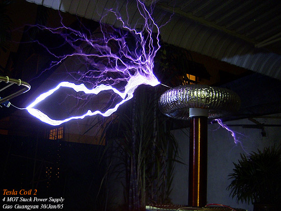
Friday, 21st January 2005
 No
updates for a long time. The new school term has been *very
very* busy. Today is Hari Raya Haji and we get a 1 day
holiday. So I decided not to put off the tesla coil for too
long and fix the power supply. As you might have guessed, the
diodes blew again. In a fit of frustration, I decided that
there will be NO MORE SILICON in the power supply! As such the
idea of the 4 MOT Stack was born. (MOT = Microwave Oven
Transformer). No
updates for a long time. The new school term has been *very
very* busy. Today is Hari Raya Haji and we get a 1 day
holiday. So I decided not to put off the tesla coil for too
long and fix the power supply. As you might have guessed, the
diodes blew again. In a fit of frustration, I decided that
there will be NO MORE SILICON in the power supply! As such the
idea of the 4 MOT Stack was born. (MOT = Microwave Oven
Transformer).
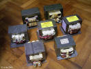
Having
accumulated several MOTs in the past few months, 7 in total,
it was time to put 4 of them to good use. I was deciding on
whether to have a 5 MOT stack of 4 MOT stack, but I
decided 4, because it's lighter and will provide enough power.
After checking the multiplying voltage of each MOT, all four,
when connected in series will give around 8600V. After looking
around, I found Greg's Page:
http://www.hot-streamer.com/greg/4pack.htm, which
had excellent information on his own 4 Stack MOT. After
modifying his circuit a little, I get this:
I have 4
unmodified MOTs. The first two have their core connected to
ground, and the primary windings in parallel. The two series
ends are connected to 4 Microwave Oven caps in series each,
which is connected to the cores of the other two MOTs, which
are separated from each other. But the primaries of the last 2
MOTs are also in parallel with the primaries of the first 2
MOTs. the Secondaries of the last 2 MOTs then have a voltage
of around 8600VAC. I measured the multiplying ratios of all 4
MOTs and the voltage will turn out to be 9 x 240.. .which is
8600VAC. So this stack will be capacitively ballasted with the
microwave oven caps (C2) and will churn out ~3kW if all is
well.
As you
can see in the schematic, I have 7 caps, not 8. Not sure if 7
caps will work. Doing some calculations, 8 caps will yeild
around 2.8kW while 7 will yield 3.2kW. I shall test and see
what happens.
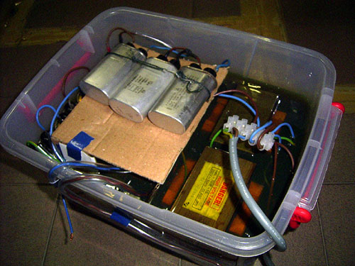
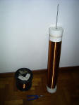
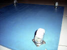
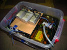
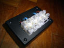
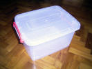  So
today I went to NTUC and bought a large Polypropylene
Container to put the MOTs in. ($6.90). The MOTs will be
covered in oil (probably motor oil) to insulate it better, and
to provide some form of cooling. So
today I went to NTUC and bought a large Polypropylene
Container to put the MOTs in. ($6.90). The MOTs will be
covered in oil (probably motor oil) to insulate it better, and
to provide some form of cooling.
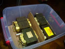
There is
cardboard around the MOTs to protect the plastic box from
scratches, and to provide insulation between the second 2 MOTs.
The cardboard will soak up the oil and everything should work
out well. I don't have enough caps so I'll be getting a few
more MO caps from a shop tomorrow, as well as a 15A relay
otherwise the 4 MOT primaries in parallel will kill the
breaker when I turn them on. Hopefully this will turn into a
good, well-behaved and reliable powerful power supply for my
Tesla coil. If all works out well, it can even power a very
big jacob's ladder! I really hope this one turns out all
right. Wasted too much time and money on the Dual MOT setup.
The only drawback in this setup is that the whole thing is
*Very* heavy... currently weighing 20kg without oil. I hope
the box can stand the weight. |
|
Saturday, 22nd January 2005
  Very
busy day today. I went to the electronics shop and spent $28
buying stuff... 4 0.83uF 2300V Microwave Oven caps for
ballasting, a 15A relay in case I need it, 6m of thick wire
(good for 15A) and many spade connectors. I went back home and
did all the wiring and arranging in the rest of the afternoon. Very
busy day today. I went to the electronics shop and spent $28
buying stuff... 4 0.83uF 2300V Microwave Oven caps for
ballasting, a 15A relay in case I need it, 6m of thick wire
(good for 15A) and many spade connectors. I went back home and
did all the wiring and arranging in the rest of the afternoon.
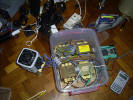
As you
can see on the left, it's very messy! I also went to the
provision shop and bought 3m of clear silicone tubing for
$1.80 for extra insulation. The high voltage wires are sleeved
with this tubing. After fixing together the wires, I plugged
in my variac at 10VAC to test... adding up the transformer
multiplying ratios, which is 9.25 + 8.7 + 9.1 + 8.9, I should
get 359.5V out... after fiddling around with the phasing for
10 mins, I finally got it right, with an output voltage of
356V, close to the predicted value! So since everything was
working fine, I went to the petrol station and got 4l of
synthetic motor oil.. it's Shell X100, and cost $20.90. It's
some thick gooey stuff which looks greenish yellow...
   I
poured it into the container until it covered the windings...
which took almost entirely 4l.. which made the box VERY heavy.
I let it sit for a while, and then put it into a plastic bag,
and connected it to a vacuum cleaner. This should suck quite a
bit of air bubbles out of the thing. I don't have a
professional vacuum chamber but this should be ok for now. I
poured it into the container until it covered the windings...
which took almost entirely 4l.. which made the box VERY heavy.
I let it sit for a while, and then put it into a plastic bag,
and connected it to a vacuum cleaner. This should suck quite a
bit of air bubbles out of the thing. I don't have a
professional vacuum chamber but this should be ok for now.
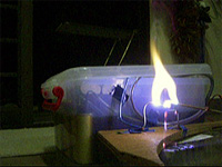
So I set
2 electrodes close together, connected it to the HV output (to
see if there were any arcs), and plugged it in with a 22Ohm
50W resistor I had lying around at the primary... it worked! I
tried again, and the resistor promptly blew apart (with quite
an explosive force!). Okay not
very smart but at least I know my power supply works. Anyway I
got the resistor free from my friend.
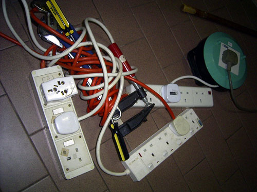
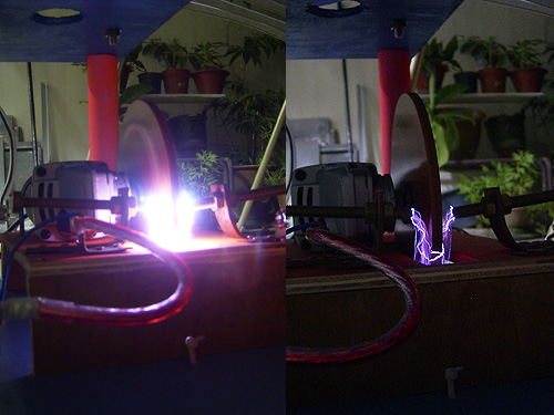
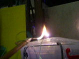
So with
no more primary resistance I just turned it on.. the breaker
held for about a tenth of a second before tripping. Not good.
I got MANY extension cords and wrapped them over pieces of
iron, as an attempt to increase inductance... well it worked
to a small extent. Not too many circuit trips. I tried to draw
some arcs.. very nice. Take a look at the video frame capture
above right. Looks just like a single MOT arc (which is
expected.. around same power level). Anyway I got some arcing
inside the box (I think it's happening on the surface of the
oil) so I added more oil (all 4 liters) and some cardboard
spacing (the cardboard will soak up the oil). Didn't have time
to test anymore so I'll do so tomorrow. I hope everything is
okay and the arcing inside will stop. I need a better box but
I guess this will hold for a long while. I'll get a bigger box
to put this box into incase it fails and all the oil spills
out. Finally, I need sometime to prevent current inrush when I
first turn that thing on. |
|
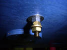
Monday, 24th January 2005
  My
friend, Raptor, suggested to me a method of 'soft
starting', i.e. limiting the current when I first turn that
beast on. The idea is simple, basically, the power to the MOT
stack is first connected through a resistor, which is
connected to a relay. When the power is turned on, the current
will first flow through the resistor, preventing a surge. My
friend, Raptor, suggested to me a method of 'soft
starting', i.e. limiting the current when I first turn that
beast on. The idea is simple, basically, the power to the MOT
stack is first connected through a resistor, which is
connected to a relay. When the power is turned on, the current
will first flow through the resistor, preventing a surge.
Then the
current will flow through the relay coil, which will cause the
relay to turn on, shorting the resistor. Even though this
happens quite quickly, the relay delay time will be enough for
a soft start. The first few cycles of the AC will pass through
the resistor first. I tried it with a 12V relay, and it works!
Next will be to try it with a 240V coil relay so I don't need
a 12V adaptor. Less wires, and more elegant. I tried to
measure the current draw, but it's very erratic, bouncing from
6A to 16A. Anyway suppose I don't get 3kW, I can always
connect less capacitors. The capacitor leads are not under oil
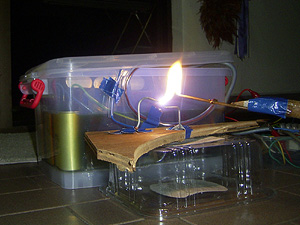
so I won't get my hands oily. Also, arcing inside has stopped!
The box is holding up well and I'm confident it can hold up
quite well as long as I don't stress it too much. Check out
the power arcs this beast can put out, without getting warm at
all. (well at least not in this short test). I took a video
and you can download it
here,
or click the photo of the arc on the top right.
The next
thing to do will be to make proper connectors for the box so I
don't need to leave a gap for the wires to go through. I guess
I'll be using brass bolt as connectors; and of course use the
more elegant mains powered relay. Once done I can put it on
the tesla coil and fire it up! I am pleased with the
performance. Arcs are similar to a single unballasted MOT, but
start further apart (4 times the voltage) and I can draw them
slightly longer. |
|
Tuesday / Wednesday, 25th /
26th January 2005
  On
Tuesday afternoon, I went to the electronics store and got
lots of stuff. I got a 4 x 5A mains triggered relay, some 15A
connectors, a resistor and some RCA audio jacks, for a total
of $7.80. Got to work once I got home. On
Tuesday afternoon, I went to the electronics store and got
lots of stuff. I got a 4 x 5A mains triggered relay, some 15A
connectors, a resistor and some RCA audio jacks, for a total
of $7.80. Got to work once I got home.
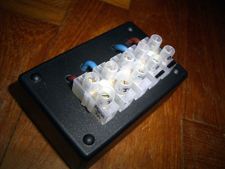
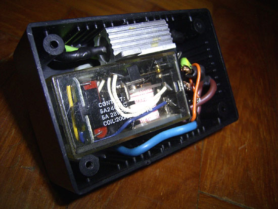
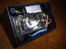
So I
wired up the soft start circuit in a nice box with some
connectors at the top. The photos show the final result. The
relay is a 4 contact 5A relay so it should be good for up to
20A. The resistor is a 25W 47 ohm aluminium resistor. It was a
rather tight fit but I got it all in. It will be connected to
the box by nylon cable ties. Tested the relay and it seems to
work. However it was getting late so I continued the next day.
So today
(Wednesday), I installed the soft-start box on top of the MOT
container. I used the RCA audio jacks for the HV connectors.
It looks nice and is easy to use. I forgot to take photos but
I'll do so tomorrow.
First
test was promising and everything seemed to be okay. However,
I tried a few more times and the breaker still tripped
occasionally! Apparently the relay is closing too fast.
However, I know what the problem is. I've wired the relay coil
before the resistor, so I should have wired it after the
resistor, which will give more delay time. Not a big problem,
I just need to switch some wires. It's getting late so I shall
continue tomorrow. Hopefully I can wire everything up right
tomorrow and plug it into the tesla coil! I should get the
coil running earliest tomorrow, but definitely before the end
of this week. I will try and post a circuit diagram once I
have time. |
|
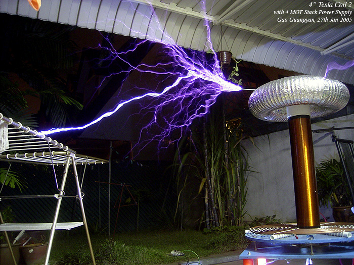
Thursday, 27th January 2005
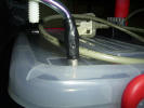
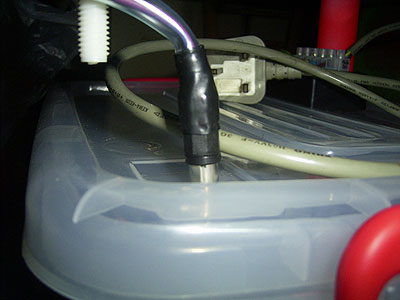
 On
the left is a photo of the high voltage feedthroughs using RCA
audio jacks. On
the left is a photo of the high voltage feedthroughs using RCA
audio jacks.
Notice
the use of clear silicone wire tubing around the HV wires.
This should be sufficient to insulate other wires from it.
Besides, it's around 8.5kV, significantly less than the 15kV
of some Neon Sign Transformers. Anyway, I fixed the relay
coil, and placed it after the resistor. Tested it a few times
and everything seemed good! I powered a nice big jacob's
ladder with it. Much better than MOTs as the voltage is high
enough for it to start itself at the bottom of the ladder.
However I didn't take any photos of that in action so.. well I
guess another time. Impatient to get the coil working, I
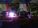
plugged the power supply to the Rotary Spark Gap (without the
tesla coil caps first)... as you can see it's quite bright
already. (Taking a photo of the spark gap while the coil is
running would be mad.. the spark gap will be *extremely*
bright. So since everything was working good, I plugged it
into the coil.
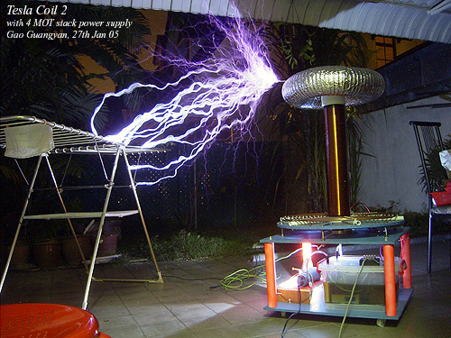 

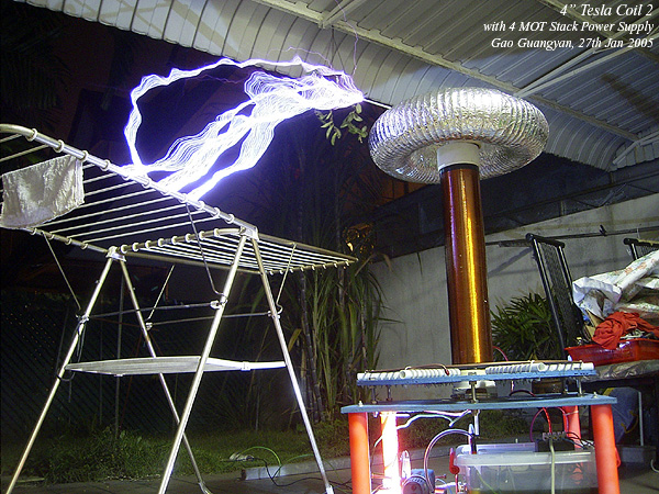
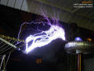
The
results are Impressive!
Check
out the 4 photos (Thumb-nailed ones) above. You can click them
to enlarge. The first one shows arcing to ground to a clothes
rack which was placed quite near. This was at primary turn 7.
Notice how thick and hot the ground strikes are! Bright
white!. Then I moved the clothes rack away and the breakout
point. (photo 2). Streamers from the toroid and some primary
strikes. Didn't harm to coil one bit but it's not so good. I
guess I need to work with a breakout point. Still very
impressive.
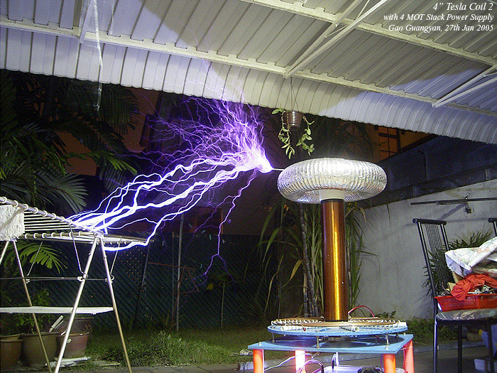
I did a
turning check and moved the primary tap to turn 6. The clothes
rack was placed just over a meter away. Results are much more
impressive! Turn 6 is better than turn 7! Arcs are over a
meter long! The 4th photo shows several ground arcs. The coil
is totally electrifying. The noise generated is insane (i need
to wear ear muffs) and the arcs are just totally scary in real
life. Success at last! And best of all, no more fried diodes,
no more tripped breakers, and excellent performance!
Now all
I need to do is to tune it properly! I believe I can achieve
arc lengths up to 150cm. As for now, I'm very pleased with the
coil. I shall insulate the wiring in the tesla coil properly
with the excess silicone tubing. Also, I hope the 25kg MOT
stack is not too heavy for the wooden base of the coil.
Today is
a good day!
Here is
a video of the coil. My camera doesn't do well in low
light situations so everything is rather dark, but it'll do
for now.
Click
here to download.
[610kb, Windows Media Video format, right click and save
target as]. |
|
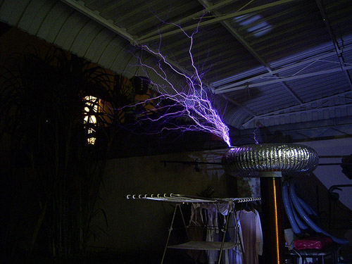
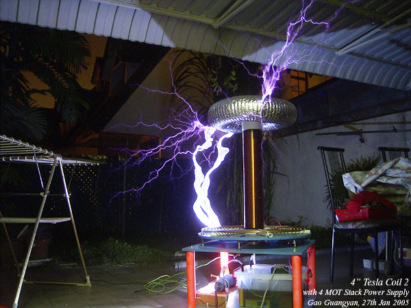
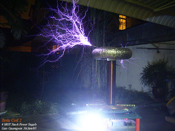
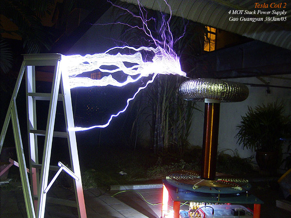
Sunday, 30th January 2005


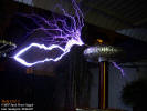
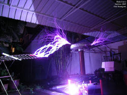
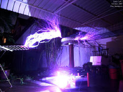
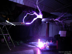
I did
some more testing today, and managed to get good results at
turn 5.5 on the primary, and I took many photos!
In the
first photo, the coil is breaking out to air. Notice how
bright the spark gap is! The streamers are longer than they
look in the photos because my camera can't capture them very
well. The second photo shows the tesla coil destroying a
ladder. I'm not sure why but many coilers like to have ladder
strikes so I might as well have one too! Third photo shows
arcing to a grounded rod. There's a big light bulb on top of
the coil, note the interesting patterns. The fourth and fifth
photo shows some longish arcs and steamers. I especially like
how bright and thick the ground strikes are.
Today's
arc length record is 110+cm point to point. Not too bad I say!
Maybe I'll remove 1 MOT cap and see what happens with the
increased power! Or maybe I can add another capacitor. As for
now, I'm very pleased with the coil. Now to push it to it's
limits and see what this thing can really do. |
|
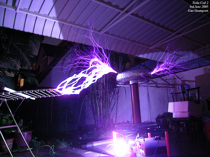
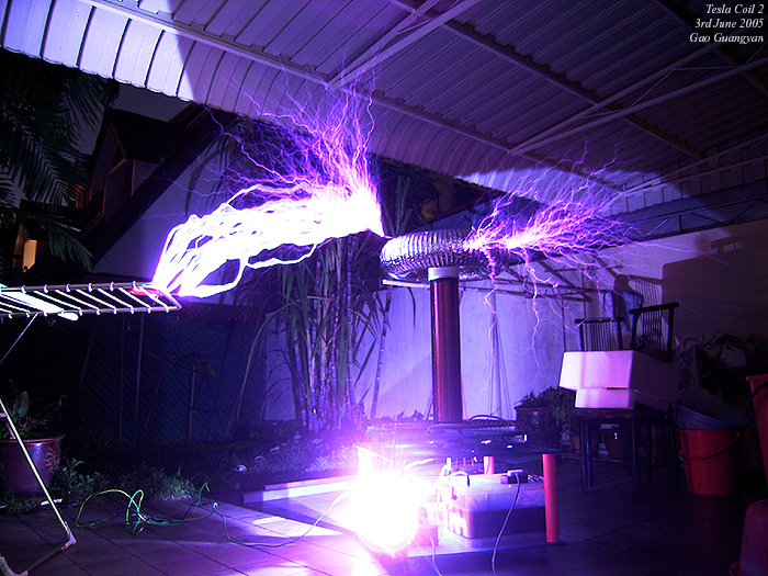
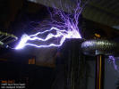
Friday, 3rd June 2005
I got to
run my Tesla Coil again, and took a few more photos. It seemed
to perform rather well! This time it didn't even trip the
breaker once and I ran it for over 5 times for quite long. I'm
pleased that it's still holding up very well. The spark gap
gets very hot, but not too hot to cause me to worry too much;
even the primary wires get warm showing that significant
current is flowing through. Performance is good! Enjoy the
photos |
| |
Tesla
Coil 2 Index Page
(c)
Gao Guangyan. Loneoceans.com
Danger! Highly dangerous! Do not attempt!
Information for educational purposes. |