Flyback Driver Circuits
High Voltage with a Television Flyback Transformer
1 Sept 2003
Table of Contents
Safety: Safety is extremely important - a flyback is not a toy!
Introduction: Basic Introduction of flybacks and the driver circuit
Flybacks: What are they? How to get one? How to use it?
- (Frequently asked question: What on earth is a Flyback?)
Flyback preparation: Get your new flyback ready for use
Circuit 1: Ultra simple Single Transistor flyback driver circuit
- Parts you will need, and how to get it working *updated!*
Circuit 2: An even simpler circuit if you have a SMPSU
Testing and Results: Pictures and Videos of experiments *updated!*
Others:Other experiments and cool stuff
- The Jacob's Ladder
- The Ion Motor*new*
- The PLASMA GLOBE (another page)
Safety
Disclaimer: A flyback is not a toy!
You must accept the fully consequences of your actions should you decide
to build a flyback high-voltage circuit!
This project involves high voltages
(several 10s of kV), which creates electric sparks that can easily jump
an air gap. Despite the generally low current of a flyback circuit, the
high frequency (several 10s of kHz) and whisper quiet operation can lead
to complacency, especially because flyback arcs can appear to be
harmless (and due to their high frequency, may not feel like much while
current is flowing!). Electrical arcs are also very hot and can set fire
to most things. Please take all proper precautions when working with a
circuit like this. This project is highly discouraged for beginners
without supervision.
Introduction
This is probably one of the best and easiest project for someone who is familiar with electronics,
but wants to venture into high voltage. It requires little skills to set
up the circuit, and only simple adjustments concerning the circuit is
required. Although the power involved may not be very high, a small mistake might cause severe
electrical burns. However, if safety precautions are taken, some marvelous high frequency arcs can be generated.
As far as I know of, this should be the easiest circuit with which a high voltage output can be achieved. The original version of this circuit used 2 transistors. Burak
(link to his page) modified it to work with a single transistor making it even easier and cheaper to build. Sam at
Powerlabs
has done the same circuit and has also achieved some very nice results
with his flyback. This circuit is reproduced from Burak's page and is of
his design (great job Burak!). Notice that it only 3 components - two
power resistors, one power transistor and requires you to wind two
windings on a flyback transformer!
Unlike a normal transformer which
operates at 50 / 60Hz, a flyback transformer is designed to operate at
high frequency, so we cannot simply connect a primary on the flyback
powered from the mains (DO NOT do this!). Instead, we need a circuit to
generate a high frequency as input to the primary coil. While the above
circuit is beautiful in its simplicity, it does have drawbacks. It
cannot be run at very high power, and the transistor tends to get quite
hot (and needs to be heat-sinked properly). Still, it is a very simple
circuit for making high voltage, and can be used to draw electrical
arcs, power Jacob's Ladders, plasma globes, and running other HV
cascades such as Marx generators.
How does the circuit work?
When power is applied to the positive
and negative terminal, current begins to flow through the resistors, as
well as through the feedback winding to the base of the 2N3055 power
transistor (for those who get confused easily, the 3 pins from top to
bottom are Collector, Base and Emitter). This turns on the transistor,
and current flows through the primary coil. As this happens, a voltage
is induced in the secondary creating our high voltage spark. At the same
time, another smaller voltage is also induced on the feedback winding,
opposite in polarity of the base voltage (you'll need to make sure to
wind the windings in the correct direction), causing the transistor to
turn off. As the magnetic field collapses, again high voltage is induced
in the secondary. Now there is no more feedback current in the feedback
coil, and once again current flows through the primary, and the cycle
repeats at its own natural frequency.
Because of this, the circuit is
self-oscillating and settles at its optimal frequency depending on the
loading. For example, as the arc is struck and drawn longer, the
frequency increases from sub 20kHz to more than 20kHz, and becomes
ultrasonic resulting in a beautiful, whisper quiet spark. See below for
instructions on how to set this up easily!
Flyback Transformers
The heat of this project is a ferrite-cored
transformer, known as a flyback. There are different types of these
transformers, and are used primarily as a method to generate high voltages
easily. As a result, they are often employed in devices with cathode ray tubes
such as oscilloscopes and televisions, to generate the high voltage required.
Because transformers inherently operate with alternating current, they often
need to be rectified with high voltage diode for use with these tubes, and newer
flybacks often contain an in-built diode. The older ones however, have
disc-shaped secondary coils, have easily removable primaries on the other side
of the ferrite core (new ones have the primary wrapped together on top of each
other), and do not have an enclosed diode (often removable). These transformers
look something like this:
Unfortunately these are starting to get more
difficult to find. New flybacks with in-built rectifiers are however useful,
such as running Marx generators, playing with ion-wind devices or charging up HV
capacitors, but are useless for experiments requiring AC output such as powering
plasma globes. Ideally you should try to find a flyback which either has a
removable rectifier (usually encased in it's own case in epoxy).
Other things to note are that these
flybacks are sometimes stepped up on the circuit board with some sort of
cascade or voltage multiplier, and therefore have a lower voltage
secondary winding. Correspondingly, you should expect no more than
around 10kV from them at most. Some of the best flybacks for making the
highest voltages can be found in old black and white TVs. The nominal
output current of flybacks are usually a few mA at most, but arc current
can increase to several 10s of mA depending on the kind of driver
circuit you are using.
But... what exactly is a
flyback?
In short, a flyback is a type of high
voltage transformer which generates high voltage of several tens of
thousands of voltages at a high frequency of several tens of kHz. This
high voltage is used to power the filaments of a Cathode Ray Tube found
in TVs or Oscilloscopes. Because they act as a transformer, there are
often extra windings on the secondary coil and provide lower voltages
for other parts of the circuit, hence the large number of pins at the
bottom of the flyback and they are used to power say the vertical and
horizontal deflection coils, and so on.
For more information on flybacks, read this excellent page.
Now lets take a look at the two main
types of flybacks.
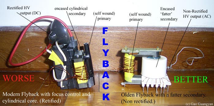
Lets take a look at these two flybacks.
Notice the modern flyback (black one) is almost completely encapsulated
with all the windings and HV diode (sometimes with adjustable output and
focus controls) encased in a black shell. Compare this with an
old-school flyback on the right with a fatter secondary. A fat secondary
is something to look out for, since the bigger it is, the more likely it
is to have more turns on it, and thus capable of higher voltage. Disk
shaped secondary coils are even better (like shown above). Unfortunately
these are more difficult to find.
To find which is the secondary output's
ground, you can use a multimeter, connecting one end to the high voltage
output (red wire for the modern one and at the side of the secondary
coil for the old flyback), and test all the pins at the bottom. The one
with the biggest resistance will be secondary ground. The other pins are
in fact auxiliary secondary windings / tapped secondary windings used
for generating other voltages in the TV or CRO, but we will not be
concerned with it for the purposes of making the highest voltage
possible!
I got my flybacks from a TV shop and
paid $5 for them, but they are easy to find in old TVs thrown out in the
trash. The general rule of thumb - the fatter the secondary, the better
the flyback for making high voltage!
Building the Flyback Circuit
Now let us get starting building our single transistor circuit.
Some preparation should be done first.
The first thing to do is to make sure your secondary
coil is not burned out and this can be done with the multimeter test as
described previously. Remember to mark the ground pin of the high
voltage output. Next, inspect the ferrite core for any defects such as
cracks - ferrite is a very brittle material and you should be careful
not to damage it. Then we are ready to wind the primary coil.
As shown above, most flybacks these days have an open
primary allowing us to simply wind the primary coil. Old flybacks may
have their own primary coil on it, which we need to carefully remove
first without damaging the core. Next is to insulate the ferrite core
(ferrite is partially conductive). we wouldn't want any high voltage
getting back into our primary circuit in the case of a secondary coil
failure! Capacitive coupling from the secondary may also induce some
voltage in the core. I wound several layers of electrical insulating
tape on the core.
Now we can wind about 4 to 6 turns of reasonably thick
wire onto the core. There is no fixed number and do feel free to
experiment to see what works best for you. I found it best to wind the
primary tightly and neatly, and then wrapping it with more tape to hold
it in place to prevent any mishaps such as it getting loose and into
contact with the secondary coil!
Your flyback should be like the diagram above now.
Next is to make the feedback windings.
This is done in the same manner and thinner wire can be used. Around 2-4 turns should be okay.
Again this depends on your particular flyback and transistor. Now your flyback should look something like the diagram shown below.
Your flyback is completed and ready to
roll! Now we need to wire up the driver circuit.
The Driver - Single Transistor (2N3055) Version
When you hook up all the components, here's how it will look like:
This circuit generates significantly
higher voltages than the flyback was originally designed to produce.
Therefore, the pins at the botton of the circuit may spray corona or
even form electrical arcs to the ferrite core! If this happens, covering
the pins with epoxy or hot-glue might help since they are not needed. It
is possible to generate even higher voltages from a flyback with a even
more powerful driver but this may cause secondary coil insulation
failure, rendering the flyback dead! Another point to note is in drawing
electrical arcs from the output. Doing this continually stresses the
secondary due to the high currents, and may also cause thermal failure,
so experiment at your own risk!
Some other points to note about the
circuit is the power transistor. The transistor WILL RUN quite hot, and
significant heat-sinking is recommended. It is also recommended that you
obtain the high wattage white-ceramic resistors for use, but they should
not get too hot. The 2N3055 should be relatively easy to find, but can
be replaced with a similar high power transistor. Finally, it is
advisable to ground one end of the flyback (the bottom end that you
found previously), otherwise significant sparking may occur at the
bottom pins.
It is extremely important that you * DO
NOT * come in contact with the high voltage output. While the output
wire is designed for high voltage, I advise moving it about with a short
plastic pole for safety.
The final piece of the puzzle is that
you will require a relatively high current 6 - 24V DC power supply
capable of supplying several Amps of current. An alternative is to use a
few Lead Acid batteries to power the flyback. The values of the resistor
are not fixed, and values for 150 to 300 ohms should work for the 5W
resistor, and similarly 15 Ohms to 35 Ohms for the 1W resistor.
Updates! 16 Mar 04
I was originally not able to construct this
circuit due to the lack of a good power supply unit... however I have recently
acquired a 34A 12VDC power supply unit! (That's 408W of power!) The circuit is
up and running!
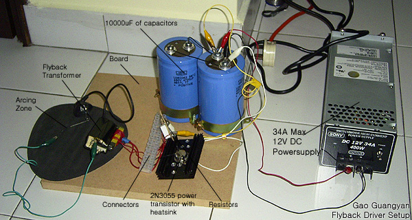
Here is a photo of my current setup. It's free standing and messy, but it works. I'll mount it in a nice box when all the fine tuning has been done. I am using a 12VDC switch mode power supply capable of supplying 34A. A car battery or a Lead acid battery would work too (and of course be more portable). The power supply must be capable of supplying around 3 - 10A,
but this would depend on the resistor values and of course the voltage
input.
I placed a large DC electrolytic filter
capacitor between the + and - of the power supply, and this is recommend
for expensive power supply units. The filter capacitor helps smoothen
out any switching noise from our circuit. My capacitors look so large
because they are 450V 4700uF capacitors, but obviously something like
25V should work fine. Several thousand uF at 12V should work well.
I am using a 2N3055 power transistor... it was cheap and easy to find, though not powerful enough for large power inputs. The resistors and everything else don't get too hot, but the transistor DOES. It becomes Very hot very quickly even with my heat sink in place. The heat sink will be upgraded to a larger one.
When everything is completed and working, there would be a small purple arc between the two terminals. The arc produces a hissing sound and is associated with its frequency. As the arc is drawn, it develops into a high pitched hiss and slowly increase in frequency until it becomes ultrasonic (above 20,000hz) and it becomes quiet. I hooked up a small flyback from a modern tv, and it starts an arc at around 1.5cm. As a rough guide to calculate the voltage, it would be about 1.1kV per mm,
giving me more than 16kV of high voltage!
When setting up the circuit, it might be
possible that your feedback winding is in the wrong direction - reverse
the polarity and try again. You should also check that the HV is arcing
to the correct return - an easy way to find out is to simply bring the
HV wire to the bottom of the flyback. The spark should suddenly arc like
crazy to one of the pins - that is the return pin you are looking for.
If all else fails, check the temperature of your secondary. If it is too
warm, you might have a shorted secondary and the flyback is no longer
useful.
More Updates! 7th June 04
The two large 4700uF caps have been replaced by
a much smaller 62,000uF 40V capacitor bank to filter switching spikes. The heat sink has also been upgraded to a huge one and the transistor is much cooler. I noticed the resistors were starting to get quite hot so I'll be replacing them with 5 or 10W resistors just to make sure they don't blow. (My 1W resistor is
turning brown!) Once everything is done, I'll mount it on a board, or in a box.
Pictures coming soon!
Circuit 2 - Halogen Transformer Version
Want to drive a flyback but don't have time to get the components or lacking a
suitable 6 to 24V power supply?
There is a great alternative! This was suggested by mws on an online
electronics forum. The secret is to use a switch mode power supply 12V
transformer such as the one below. The photo below is from him.
Parts List:
1. Insulated Wires
2. A Flyback
3. A SMPSU (Switch Mode Power Supply Unit)
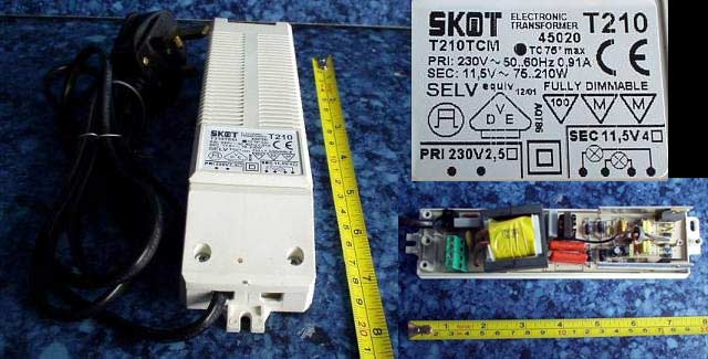
Electronic 12V halogen transformer. These are used for 12V halogen lights, and different from normal iron-cored transformers (which run at 50-60hz and are thus not suitable,
and are much heavier!). These are electronic transformers with lots of components inside.
These electronic transformers deal away with the
heavy iron core of a normal transformer and run at a high frequency of around
20kHz to reduce the size and weight. Because of this, they output a high frequency, low voltage current that just happens to be perfect for driving a flyback!
Above is what a good electronic transformer would look like. In this case,
it has an output of 11.5VAC. This model supports a hefty 210 watts. All we need for an excellent flyback driver! However, in where I live in, it is difficult to obtain such a SMPSU. So I am currently using a
smaller 50W electronic halogen lighting transformer. Try to get the good models (above 70W). Apparently, where I stay, I can't find any shop selling high powered electronic transformers so I am stuck with
poor 50W transformers which can blow up if run for extended periods of time.
What do do now?
1. Wind the Primary Coil
You need to make the Primary Coil -
this is only slightly different from our single transistor circuit. Insulate the core with many layers of good insulating tape first. Just wind around 10 turns and tape it all in place. If you experience any problems with the output, you may need to add a few turns to your primary. If there's not enough inductive reactance on your primary, you may be triggering the protection circuit. Most
SMPSU / electronic 'transformers' have a protection circuit. Anything from 5 to
15 turns will work. Then again, fewer turns would result in a higher voltage
output, but have heavier loading on the power supply.
2. Connect them up!

Follow the diagram above, and wire it up... and you're done!
3. Locate the HV ground pin
Now all you have to do is locate your high voltage return pin. Simply turn the unit on, and very carefully bring the high voltage output wire down to the pins on the bottom of the flyback. The pin that it arcs to
it like crazy is the pin you're looking for. You'll want to attach a length of
wire to that pin to prevent it from getting too hot and melting.
4. You're done!
It's completed! Your ultra simple flyback driver which is easy to build and use!
Testing and Results
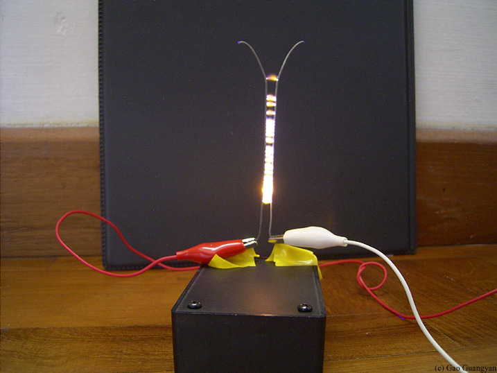
1st September 2004 - Testing using a non rectified flyback driven by a 50W halogen light transformer. (Circuit 2)
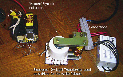
Here is my ultra simple setup! Due to lack of a good Power Supply for the single transistor circuit, I am using a
cheap Electronic Halogen Lighting transformer, 50W and Liyoda brand. I will be using the good old flyback (white one) for the experiments. Also, remember: never, let the HV lead or the flyback itself get close to any of the primary side components
or risk blowing up your power supply! *Updated.. I have fixed together a new single transistor circuit.
*
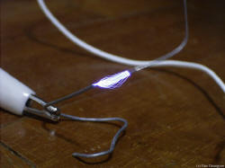 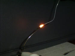
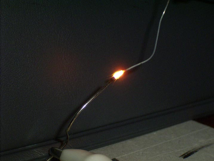
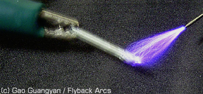
Above you can see a pictures of the flyback operating. The output voltage is close to 20+kilovolts, which is enough to ionize the air without any ground nearby, as can be seen. The corona extends up to
5 mm into the air, and once struck the arc can be pulled up to little over 2 cm. It makes a loud hissing sound. In this 1/2 second exposure, the electrical arcs can be seen arcing to ground. The rightmost picture is a 1/42 second exposure with flash. It's a bright HOT arc
when placed close together! The metal electrode is currently red hot and ready to melt. Lots of sparks.
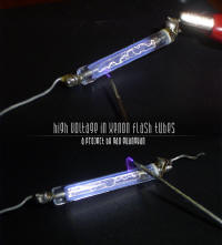
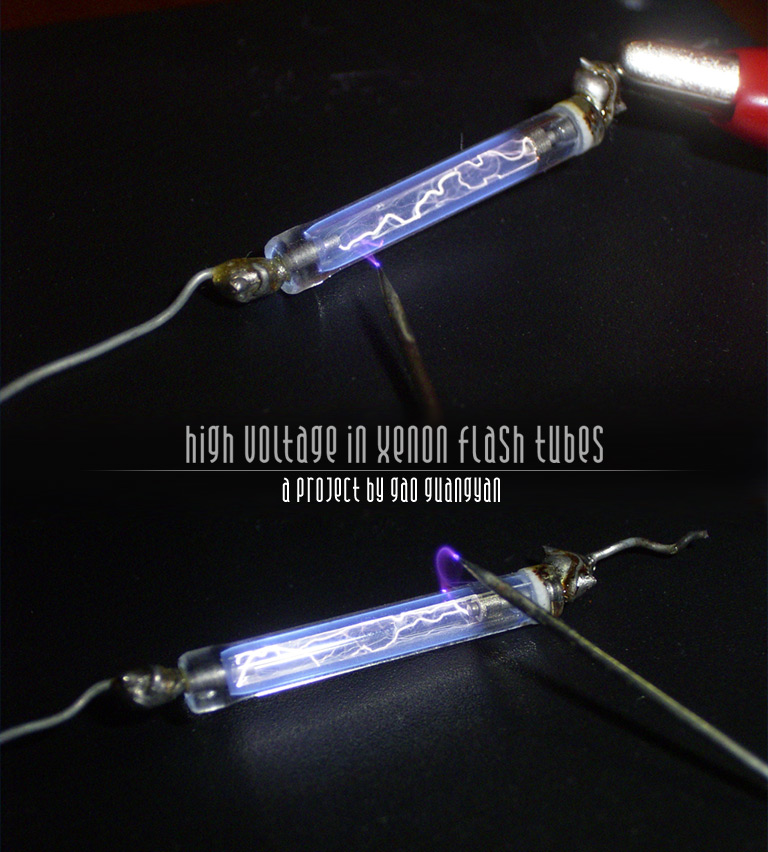
Finally, some nice arc pictures through xenon tubes.
Updates 16th Mar 04
 Due to my latest acquisition of a 408W 12V power supply unit, I am able to carry out the more powerful single transistor driver experiments. As expected, there was a significant improvement over the 50W lightning transformer driver. The arcs look different (less lightning like) and have a characteristic hissing sound associated with its frequency. A much higher voltage is obtained and the arcs can be drawn longer as well. Due to my latest acquisition of a 408W 12V power supply unit, I am able to carry out the more powerful single transistor driver experiments. As expected, there was a significant improvement over the 50W lightning transformer driver. The arcs look different (less lightning like) and have a characteristic hissing sound associated with its frequency. A much higher voltage is obtained and the arcs can be drawn longer as well.
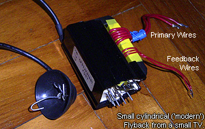
It is more powerful and much higher voltages can be obtained. I am currently using the smaller cylindrical type ('modern') flybacks,
which was another one I got it for $5 at a TV repair shop, and it was supposedly
used in small black and white televisions... so hopefully it'll be good!
The output cable is rated 20kVDC only
(printed on the cable), compared to the 40kVDC cable from my bigger flyback, from a large colour TV. However, with 5 turns on the primary, the smaller flyback produces longer, hotter and more powerful arcs... and of course a higher voltage, than the bigger flyback! I am very happy with the performance of this small flyback. It is small and reliable. I might try getting another similar transformer and winding it in an anti-parallel configuration for higher voltage, but not just yet.
As can be seen from the picture, I wound 5 turns as the primary, and 3 turns as the feedback. I might change the primary to 4 turns to get a higher voltage though... anyhow, the flyback works wonderfully and produces nice hissing purple arcs. Now the photos :-)
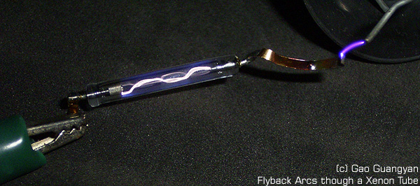
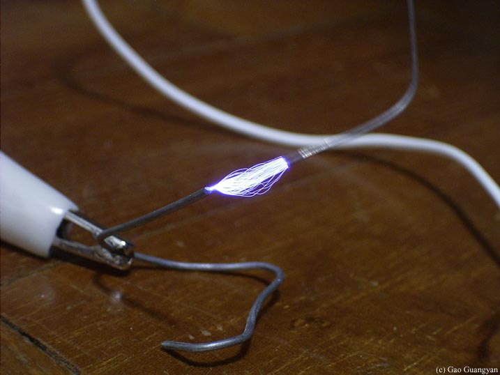
This is a xenon flash tube from a disposable camera. You can see the purple arcs from the air, as well as the interesting white arc patterns in the tube. The tube gets hot quite fast obviously... I learnt it the hot way...
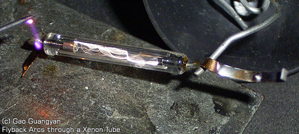
Another lovely photograph of the arcs inside the xenon flash tube. Both air and xenon arcs are clearly visible.
Arcs of the flyback. It is difficult to focus accurately... meanwhile, this photo should do. The arcs are much more purple in reality.
Flyback Videos
It is a must to view the flyback videos. Although it's big, it's worth the wait!
Download the Loneoceans Flyback Experiment video 1 now! flyback.wmv (2.78Mb. Requires Windows MediaPlayer)
(Left click and select 'save target as' to your hard disk)
Video Explanation:
The video is in 3 parts.
In the first part, you can see electrical arcing between the two electrodes. That's a 2cm arc. Almost 30,000 volts and can be drawn up to 4cm long. The second part is a close up of the arcs MELTING the electrodes. The third one is an overview. MUST see! The flyback used is the fat white one, and is powered by a 50W halogen light transformer.
More Experiments
Now you have this circuit running, and you have played with it's beautiful arcs,
set some things on fire and found that it could light up a fluorescent tube... and you wonder what it can be really used for...
Well, you can start off by adding a full wave rectifier to make the output DC, which can than be used to power ion motors
(see below), charge capacitors (or just use a modern rectified flyback),
or build a Marx Generator!
The non-rectified flyback can be used to power Jacob's ladders, light up plasma
globes, and much more... With a cascade, very high outputs can be obtained. But first, make sure to check my plasma globe page to see an awesome use for this device! Otherwise,
continue to look below to see my flyback powered Jacob's ladder!
Jacob's Ladder
What is a Jacob's Ladder?
A Jacob's Ladder is a type of high voltage "climbing arc" display seen in many old Sci-Fi movies.
They come in all shapes, styles, and sizes. So how does it work? The simple explanation is that an arc starts at the bottom and due to the fact that hot air rises, tends to move up the diverging rods until they are too far apart for the voltage
to be sustained by the power source. Once this arc is struck, the current in the arc will
increase to the transformer's limit.
Normally the transformer would try to bring the voltage down as current increased. But just above the arc exists a path that the transformer can easily maintain and which in fact will lower its current. At the top of course we are not only at the upper limit of the transformer but it is also where the current is very low and so the arc breaks apart only to re-ignite down below.
However, there are some dangers. The electrical discharges in air produce ozone which may be a health hazard. Also note that the rods get very hot! Always allow them to cool down before adjustments.
I got to work by quickly setting up two metal wires and connected them to my
flyback.
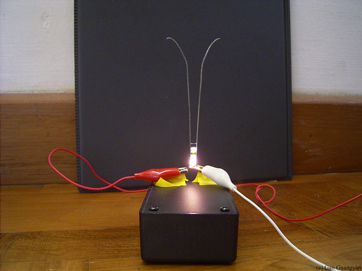
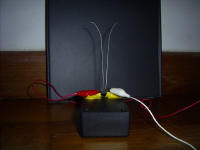 Here you can see my Jacob's Ladder setup. Here you can see my Jacob's Ladder setup.
It's two stiff wires bent and stuck on a plastic box (base)
The red wire connects one end to the HV lead of the flyback and the white one is connected to ground. As you can see, it's really small, simple and easy to make. I did the whole set up in less than a minute.
The background is a black file so the arcs can seen more easily.
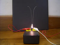 First light! First light!
Nice, HOT bright arcs form. Not bad at all! Here you can see it starting from the bottom.
(Apparently, my measly flyback with a pathetic power supply can't generate large arcs, also, the bottom wires were too close and it kept re-igniting before reaching the top.)
... after some simple adjustments...

MUCH better!
Here in a 1sec exposure, you can see the arcs rising up towards the top and extinguishing. After continuous use, the smell of ozone becomes apparent and the wires get really really hot.
By coating wires with salt, bright yellow arcs form instead of the orange, fiery-like arcs you can see here. Using other salts also yield different colours.
Here is an short sequence animated GIF of the arc going up the ladder. (400+kb)
 This is basically a diagram of how I wired everything up. It's very simple actually. I've tried for both AC and DC and they both work fine.
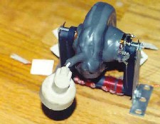
The Ion Motor
16 Mar 04
*This will only work for DC, which makes this an extremely useful toy to make if you have a
modern DC flyback!
Here you can see a simple diagram of the construction of a ion motor. The stand the the wire (yellow) are conductive. Bend a wire as shown in the diagram. The wire balances on top of the stand, with the tips pointing in different directions. When a high voltage is applied, there will be a hissing sound and ions will start to spray off the sharp end of the wires. This propels the wire in a circle and keeps spinning. The speed can be amazingly quite fast!
Click here to download a 857kb, 30 second video on the ion motor.
Back to main page
(c) Gao Guangyan 2011
Contact: loneoceans [at] gmail [dot] com |