A first project with the Arduino Microcontroller Platform
* System Updated in 2017! *
22 Feb 2011
Arduino Musical Lighting System (V1 and V2)
Introduction
This project was motivated by a desire
to light up my dorm room in college. The common dorm room usually comes
with a little fluorescent lamp in the middle of the room providing general illumination, but just barely. My room in Next House was no exception. Yet the idea of buying a little table lamp was unappealing. Earlier on in the semester, I had acquired a set of three 20W Halogen lamps and they added much warmth and comfort (everybody loves
Halogens!). Still I wanted a bit more dynamism and colour - not simply
to install additional lights, but also to bring a little more flavour and piazza to my room. Afterall, I was
in a tech school.
In the early spring of 2011, my dorm held its first event in a
while - Impulse, which was a party at the basement
level. The cool thing about the party was the custom lights - a $2000 investment that the house had given to a group of students to design and build a party lighting system. It was extremely successful, and made me recall the amazing dancing lights I saw at another dorm room a few months back (TEP).
So I decided to build my own musical lighting
system! This page documents the journey I went through to make this.
Update End 2011: Just
less than two months after I conceived of the idea, the
home-made audio-modulated dorm lighting system was born. The result is showcased
here with extra incandescent lights synced to the bass. For more information, refer to the project log and notes below.
Update Start 2017:
It has been six years since I started this project and it's time for an update!
The update includes several improvements including a revised and tided
up light bar with new LED colours, improved driving
algorithms & firmware for less latency, and a completely new integrated
circuit board removing the need to use an actual Arduino Uno (but keeping the
same general schematic as the original), and additional functionality. Scroll down for more
information!
Design Considerations (Version 1)
The goals of this project were straightforward. I decided to adopt the Arduino development platform using the Arduino UNO board running a ATMega328 Microprocessor.
This was chosen due to its low cost, ease of use, fantastic documentation and versatility.
This was also my first project with the Arduino platform so it
would be a learning experience for me as well. I also decided to try out first hand the new high-powered LEDs which
were quite expensive just a few years ago but now available at really
low costs from Chinese distributers like DealExtreme.
The principle of the music visualizer is simple -
stereo audio from a 3.5mm stereo jack is sent from a computer or an MP3 player into the
analog input of a microcontroller. The microcontroller reads out the waveform and performs a frequency decomposition into several different frequency bands. The microcontroller then takes the amplitude of each frequency band and uses it to modulate the brightness of one of several ultra-bright LEDs using Pulse Width Modulation
(PWM). Since the microcontroller cannot output more than
40mA safely, MOSFETs are used to switch the high-powered LEDs, and eventually, Halogen
or regular incandescent lighting.
[update: this was later extended to general lighting systems such as
standard line lamps / bulbs]. Finally, I know I can purchase a similar
musical lightning system online but that's not quite as fun as building
one myself!
These are the goals of the project:
To design and construct a simple and portable lighting system with ultra-bright LEDs
Allow modular implementation for extension to other lighting systems, e.g. Halogen lamps
/ 120V or 240V bulbs
Learn to use the AVR microcontroller system via
Arduino
Implement a basic but effective lighting algorithm for first version of system
Incorporate more complex and fancy lighting algorithms for subsequent versions
With these few ideas in mind, the project begins!
Project Log
Feb 2011
Arduino Uno arrived today. I bought an Arduino
Uno on Amazon.com for $29.95, but I had a $20 discount voucher which
I spent $10 buying. Unfortunately I can't work on anything else now
because I'm still awaiting some other components. Spent some time
reading up about the basic functionality of microcontrollers. This
is after all my first real microcontroller project.
2nd Mar 2011
After some initial research, it was apparent that standard implementations of Fast Fourier transforms run
somewhat slowly on the Atmega328. However, I discovered that there exists a 7-band graphic
equalizer filter IC which will be able to filter out the 7 frequency bands of my input audio, and it all comes nicely in a small 8-pin IC! This is the MSGEQ7 graphic
equalizer filter chip. I couldn't find a cheaper and easier place to get the MSGEQ7 graphic
equalizer filter so I ordered some from Sparkfun electronics. The MSGEQ7
was $4.95 each.
I haven't decided which LEDs to buy yet, but it seems that the LEDs I am currently interested in
from DealExtreme run at about 3V (varies with colour) and (have conflicting reports) of it being driven from 300 to 700mA, at which they run quite hot. Regardless,
the microcontroller output pins can supply no greater than 40mA. In order to switch the bright LEDs, one could use a transistor like the TIP102 or TIP120 (darlington
transistors), but I decided to go for a standard logic level N-Channel
MOSFET
RFP30N06LE. It is rated for 60V at 30A and is an overkill for the project,
but they were easy to get. If all goes well, I should be getting the components in about 1 or 2 weeks.
Next up on order are the powerful 1-3W LEDs, which will probably be from DealExtreme.
4th Mar 2011
After sorting out the initial plans for how I would want to make the lights, I ordered some powerful LEDs from Dealextreme. I do not know the exact power rating
the LEDs are but they have been claimed to be driven u to 700mA, which works out to be over 2W input per LED. The plan is to have 6 powerful LEDs of different
colours corresponding to the six output frequencies from the MSGEQ7.
These will be: White, Red, Yellow (white with gel), Green, Blue, Purple
(White with Gel). I also purchased a few other spare components. These
components are:
3W Multicolor LED #4530 $2.74 ea.
Red CREE LED Emitter #1776 $3.64ea.
Blue CREE LED Emitter #1775 $4.11ea.
Green CREE LED Emitter #1777 $4.21ea.
White CREE P4 LED Emitter #1302 $2.93ea.
5mm UV LEDs x20 #2398 $3.07 for 20x
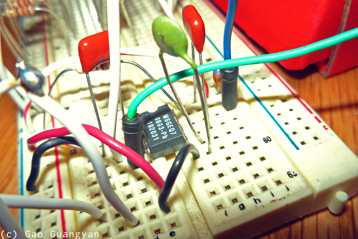
11th Mar 2011
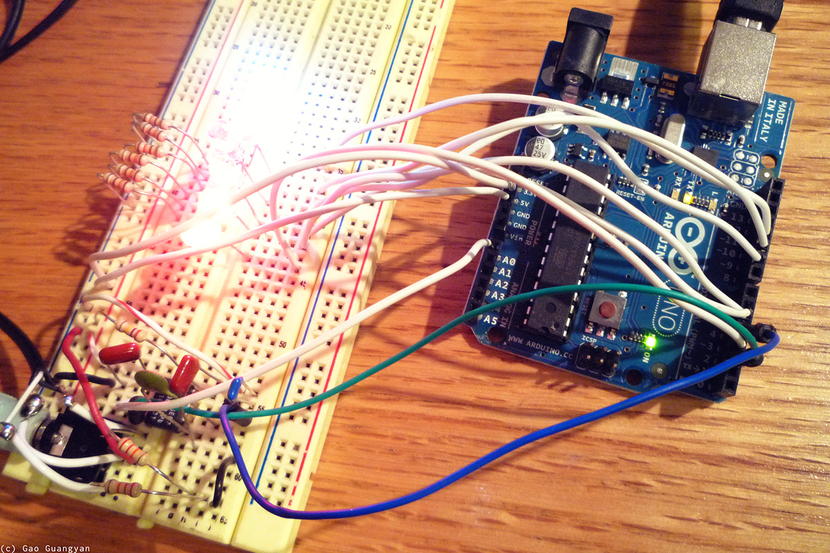
Today I finally got started working on the project since I had received some of the components and could begin. I got a breadboard and started laying out the circuit. The
initial plan is to use the MSGEQ7 spectrum analyzer which is a 7-band filter and will output the amplitudes of each frequency band based on a driver frequency.
Setting up the circuit was relatively straightforward. One channel
(out of two from the Stereo input) was used and the signal was sent to the graphic
equalizer filter. After a few quick initial tests, I got the circuit
working as planned. The MSGEQ7 outputs the amplitude of the frequency
band as an analog voltage which is read by the microcontroller via it's
10-bit ADC. Right now I'm just dividing by 4 (fast binary operation) and sending it as a 8 bit value to the Atmega's Pulse Width Modulation output. Since the ATmega368 only has 6 PWM outputs, I connected
only 6 LEDs to the output and ignored the last highest frequency band.
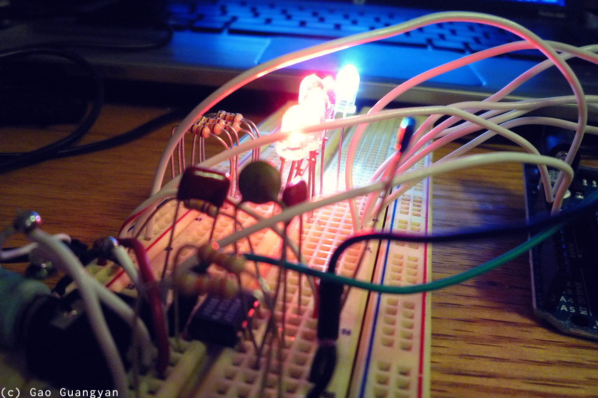
First
Result: the circuit works! The most
important observation for now is that the output of the LEDs is are not 'contrasty' enough. This is expected since the
'brightness curve' as it stands is linear (with relation to audio
brightness), but our eyes have a somewhat logarithmic
response to light brightness. More work will be done soon to fix this. School beckons.
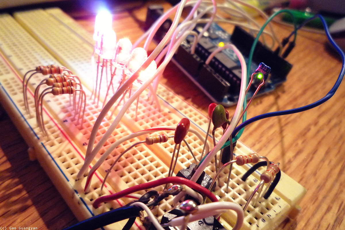
20th Mar 2011
A quick improvement. I didn't have much time so I just did some small tweaks to the
modulation code. This has mostly got to do with the 'contrast curve'
After some experimenting and looking at various graphs, I've settled on
a Sin(Sin^4) curve, but will probably optimize it further for better
performance (speed).
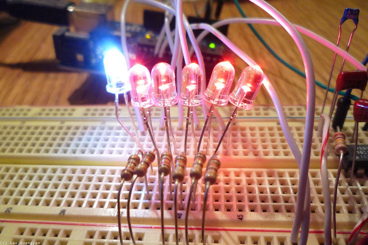
I also found a white LED and used it for the bass. I recorded a short video of it in action. Now all I need is to await the bright LEDs to connected up via the
MOSFETs. :)
29th Mar / 1st Apr 2011
Have received the bright LEDs from dealextreme! This week (at least till Wednesday) is a bit busy so I hope to begin at least wiring up the LEDs and the
MOSFETs within the week :) ...
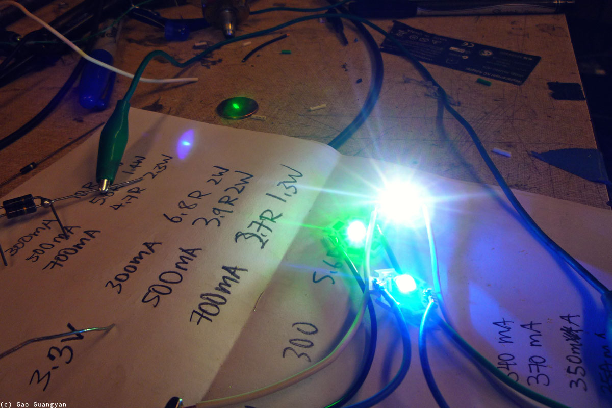
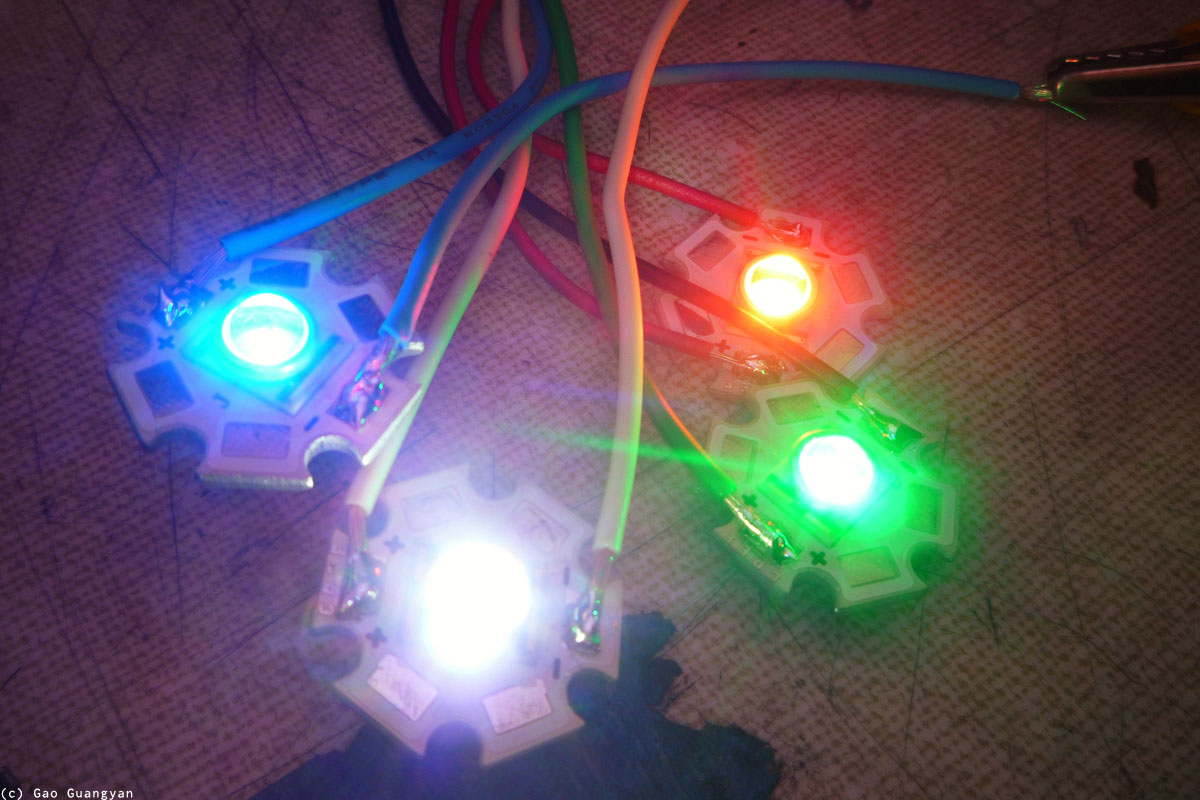
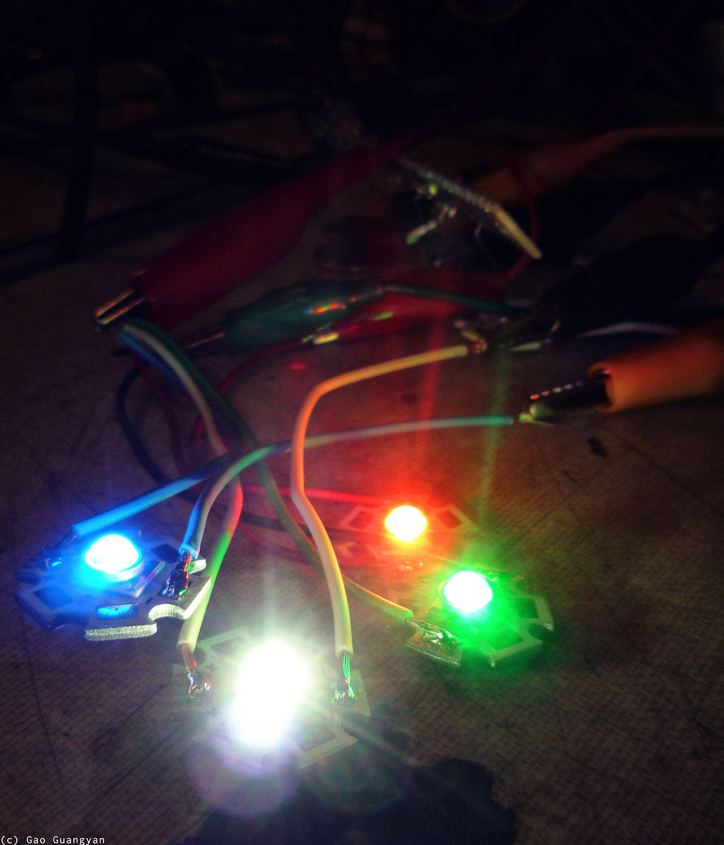
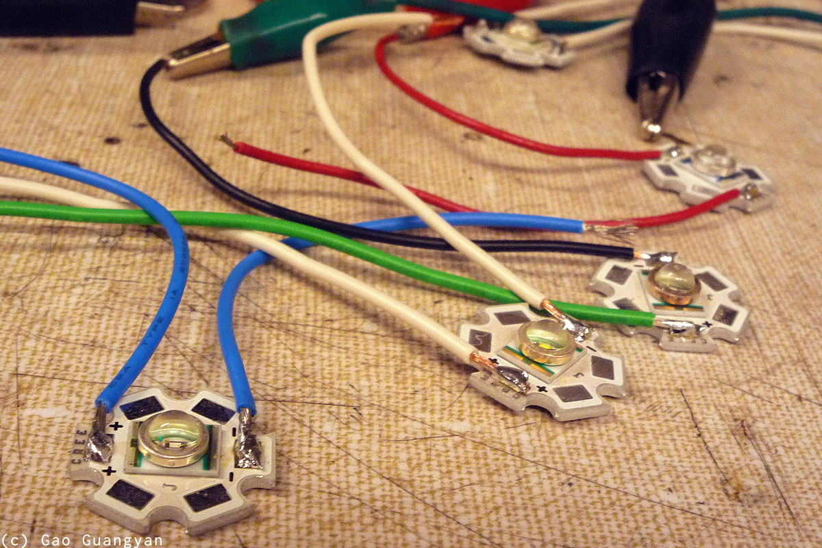
[Update 1st Apr] It's April Fool's today! However, not much stuff was going on in school. I headed over the MITERs, a little workshop in my school, and soldered the LEDs to wires for easy connection.
I also did some tests on how uch current I should be sending into the LEDs.
(I do not know exactly what the part numbers for the LEDs are except that they are CREE LEDs). The specifications actually seem to read that they are capable of 750mA input each at varying voltages, but I've heard reports that they run really hot at that current, and most people are fine with 300mA. So I plan to run them at 350mA each. Now it's time to make a mount to hold all of them together!
11th Apr 2011
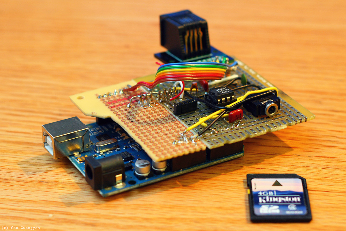
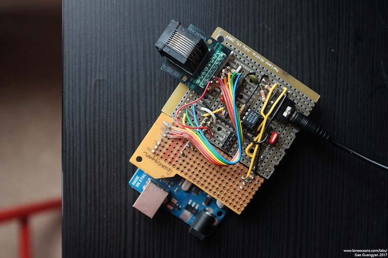
The first phase of the project is complete!
Once I got the project tested on the
breadboard, I made a quick 'shield' for the Arduino just for easy plug
and play. I ran out of perf-board so I simply used two leftover pieces.
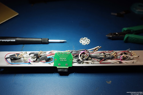
The board contains the spectrum filter IC as well as a stereo input. To
connect to the main lighting strip, I simply used an Ethernet RJ45 jack
which has 8 wires in one easy connector. This choice is arbitrary and
far from optimal, but was simply done out of convenience.
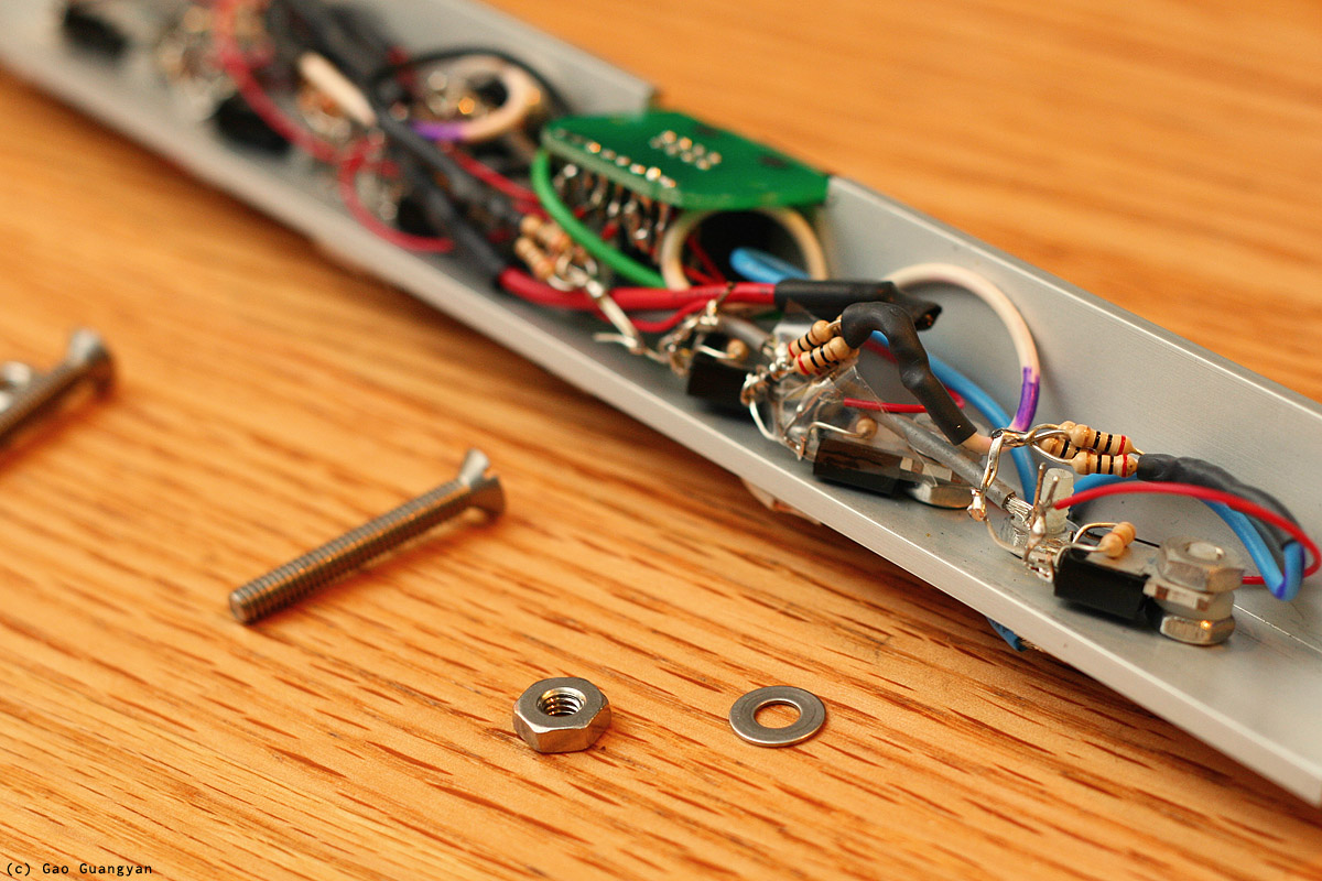
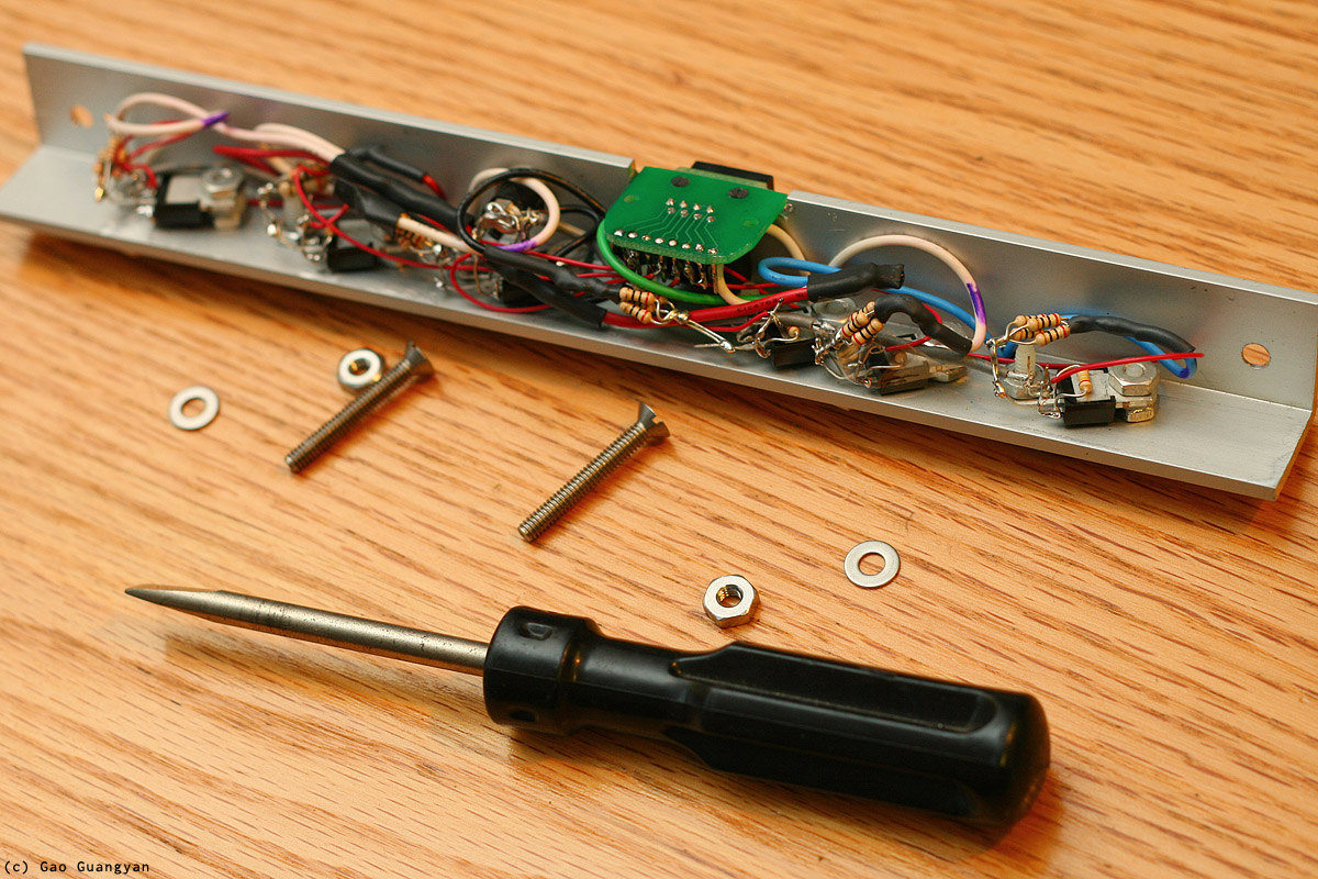
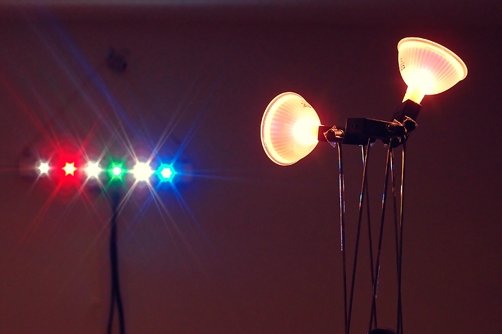
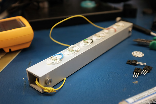
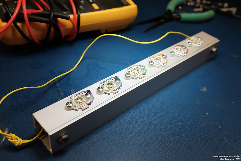
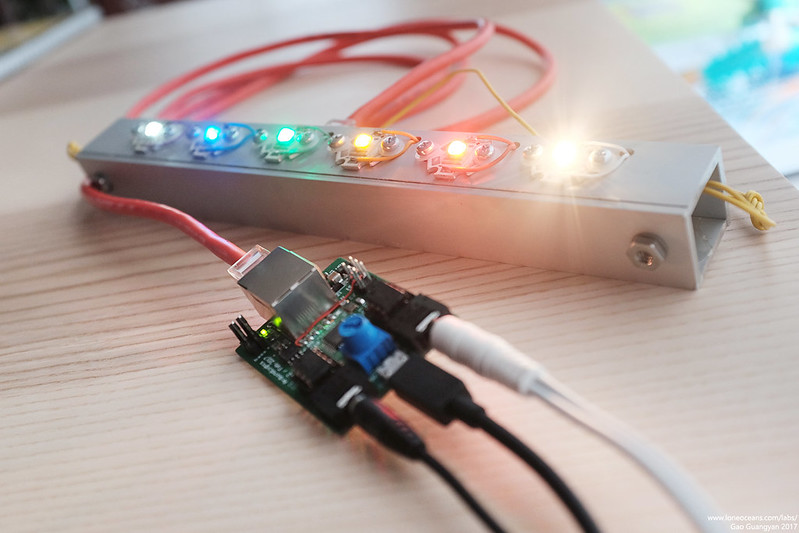
The corresponding piece is the main star
of the show - a 6-led Light-Bar which contains the 6 ultra-bright LEDs of various colours, a
5V 1A input jack for the power, along with the drive transistors and
another Ethernet connector. This allows easy connection to the controller
board. I machined this carefully by hand using some aluminium L-bar and
they were carefully milled inside to accept the electronics.
Finally, I added some external bass output headers for future expansion!
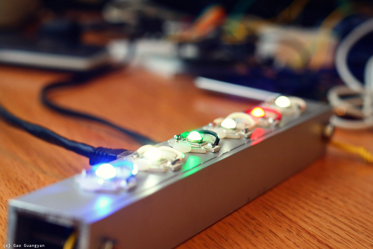
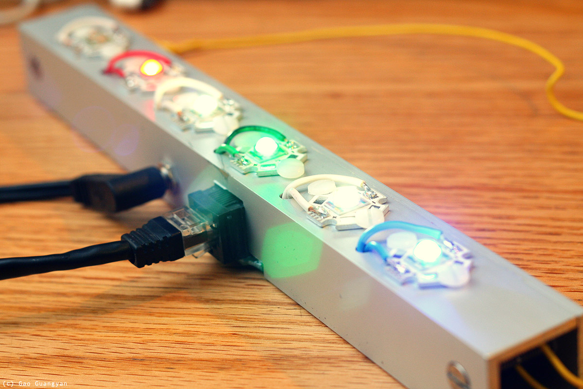
This all came together quite well and I'm very happy with how my
light-bar came out.
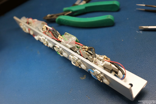
Here's how it looks like inside (photos above), and with the lighting
system running!
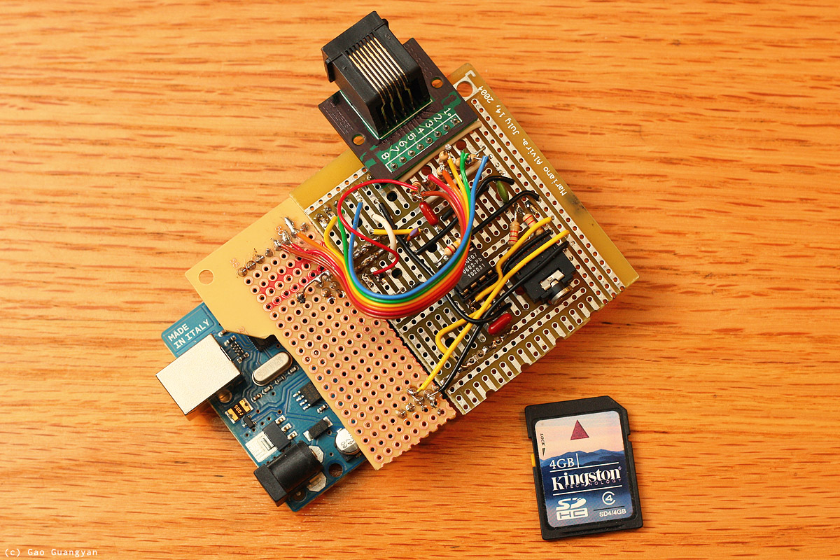
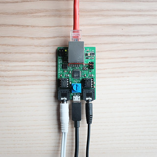
[Update] Above is another photo of the completed board
(photo actually taken 6 years later in 2017!). A little bit of a shoddy
construction built with junk parts I had on hand but it does work!
Extensions to come soon to extend control to
normal 120V light bulbs around my room. This can be easily extended
as a computer / remote lighting system controller or any other system
for that matter. It all works and does look quite pretty if I may say so.
:-)
Extensions - Halogen + Incandescent Bulbs
Late Apr 2011
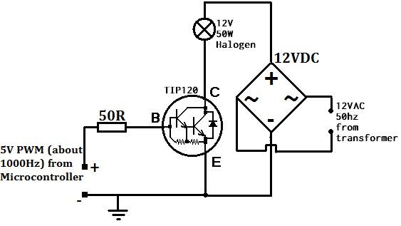
TIP120 Darlington Transistor
Since the LED lights were so successful, I decided to do a
quick extension to the project and wire up the set of three 20W halogen bulbs I had. I think the lights will be nice if they respond to the bass, so I spent an hour or so wiring up a quick circuit to put in series with the halogen lights and the 50W 12VAC halogen transformer. I had ran out of
MOSFETs so I decided to give the TIP120 a try. The TIP120 is a common NPN Epitaxial Darlington Transistor, which is basically two transistors
cascaded together, allowing a
large current gain (i.e. use a really small current to switch a big one). The
Darlington configuration allows a much higher switching load compared to just a single one.
TIP120 wired to Halogen Lights - Do not use this, a
MOSFET performs much better! More details below.
This particular transistor is rated at 60V 5A, with Emitter-Base voltage of 5V and DC
Current Gain of 1000. The 12VAC was rectified via a bridge rectifier and the output connected to the TIP120, which was mounted on a heatsink. The basic wiring diagram is as above. Note that it is important to connect the
grounds together. With everything set up and the bass connected to the PWM output for the bass frequencies, the lighting system was switched on.
Unfortunately, the setup performed poorer than expected. The TIP120 got really warm quite quickly even with heat-sinking
and the lights never really turned off - they just got brighter and
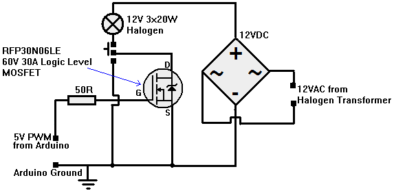
dimmer. It was clear that a MOSFET would be better. I eventually sourced
another MOSFET for the Halogen Lamps and put everything together on a nice heatsink (mostly for the bridge rectifier which was a 34A 800V one I had lying around) and connected it up to the lamps and Halogen transformer.
The circuit is as follows.
Replaced the TIP120 and used the 30N06 N-Channel MOSFET. Also added a switch allowing me to toggle between Always-On and Modulated. Works great!
[Update : Don't use this, instead, use my general purpose isolated drive
circuit below!]
This new circuit is essentially identical to the LED
setup. It works wonderfully well now and was fun to listen to music
together with. See a video of it in action here:
7 Sept 2011
IRFP460 120V Incandescent Bulbs (see next
section for better, safer circuit)
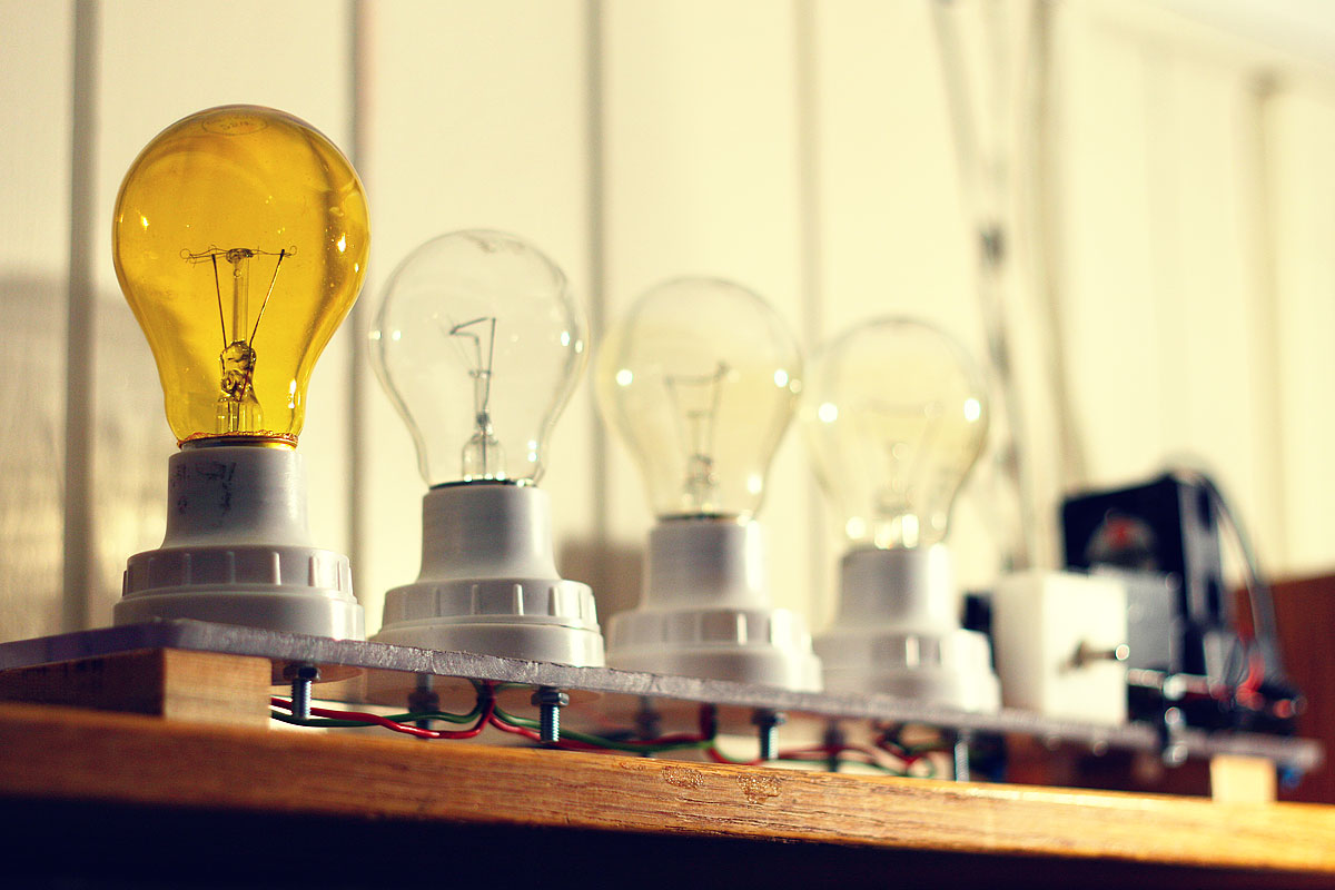
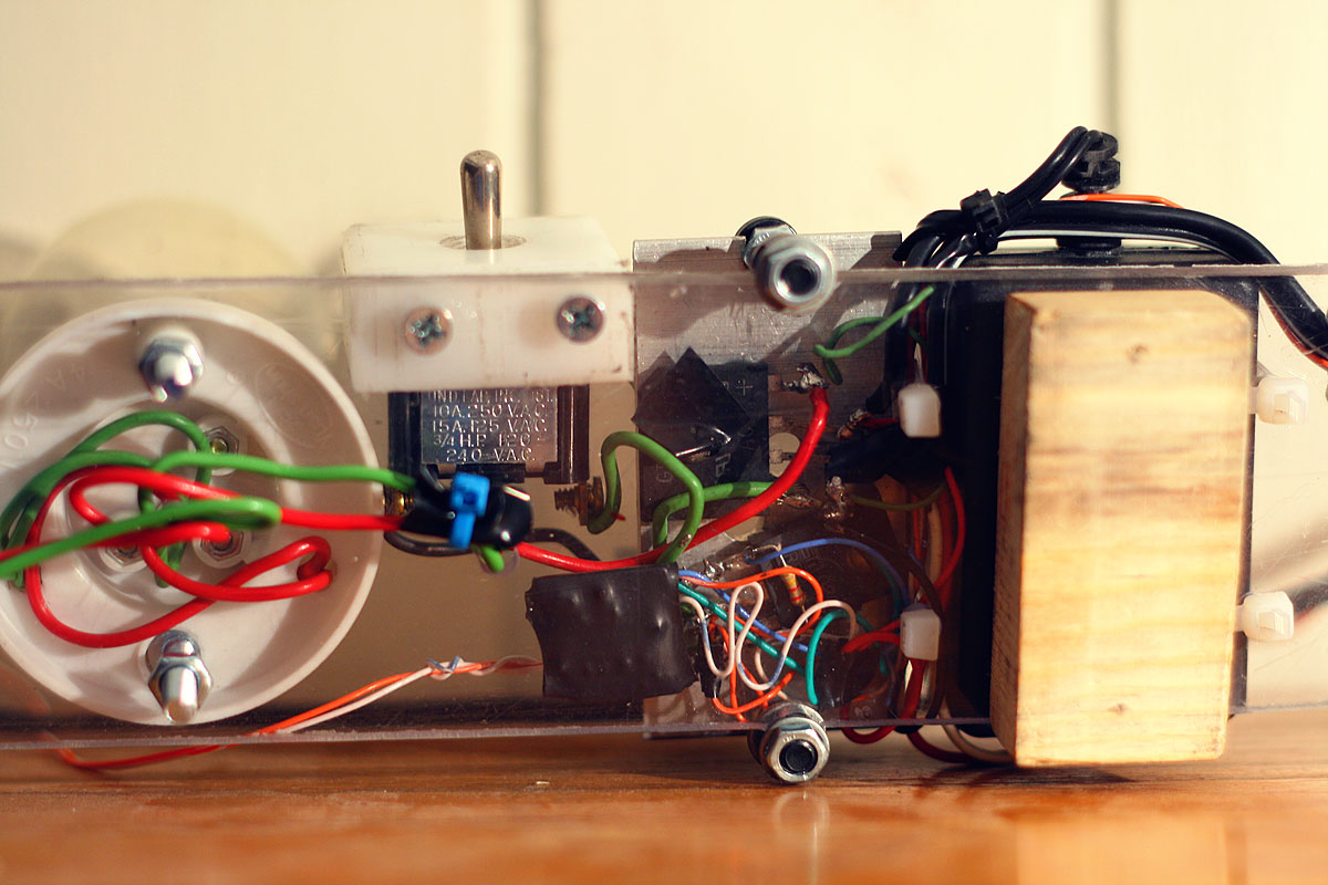
I got back to school on the 2nd of September and immediately got started on working on a new extension for my lights. This took a single 4 hour session as well as two more trips back to the workshop to get the circuit
tidied up. The idea this time was to use the same signal to power an array of tungsten bulbs - not from a 12V supply, but bulbs from the mains
(120V). This will allow me to use a row of cheap and nice light bulbs and should work great with the bass. Junk materials were used - a left-over polycarbonate board was machined to hold 4 bulb holders and the entire setup raised on wooden blocks. The heatsink was then mounted with two bolts and the small 12V supply with cable ties.
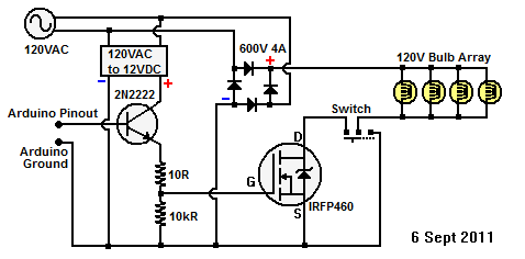
The question then is how to switch 120V with 5V? I had some very nice IRFP460
MOSFETs lying around, good for 500V at 20A, and decided to use them. :) The problem is that these normal
MOSFETs require around 10 to 20V
on the gate to switch.
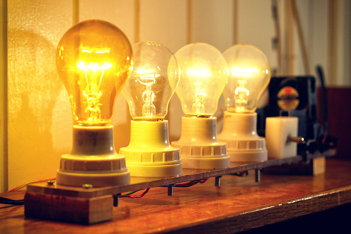
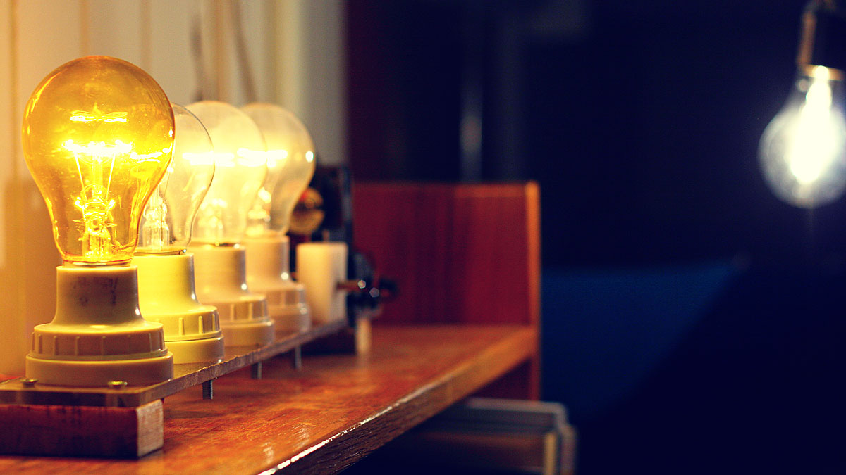
I used 3 100W 230V bulbs (had to use a 25W 120V yellow bulb because I only had 3 100W bulbs) running on a 120V line to give
the bulbs a warmer glow. In comparison, the bulb in the background is a 72W halogen so you can see how comparatively warm
the 100W bulbs (under-driven at 25W) are, exactly the intended effect!
The original solution called for using a simple N-Channel 2N7000
MOSFET (very cheap and very common) to trigger the gate. The problem is that N-Channel
MOSFETs should act as a 'low side' switch and wiring them in series with my IRFP460 would create a logic inversion, i.e. no signal from
micro --> lights on; signal --> lights off; which is not what we desire.
Eventually I settled on a rather unusual way of using an NPN transistor
(2N2222) triggered by the micro to a resistor-voltage-divider. The
2N2222 sends current to this divider from a separate small 12VDC power supply which triggers the IRFP460.
(Update: This is a very dangerous circuit!
DO
NOT USE THIS - I've merely included it here for completeness)
- NO ISOLATION: Do not use this circuit! -
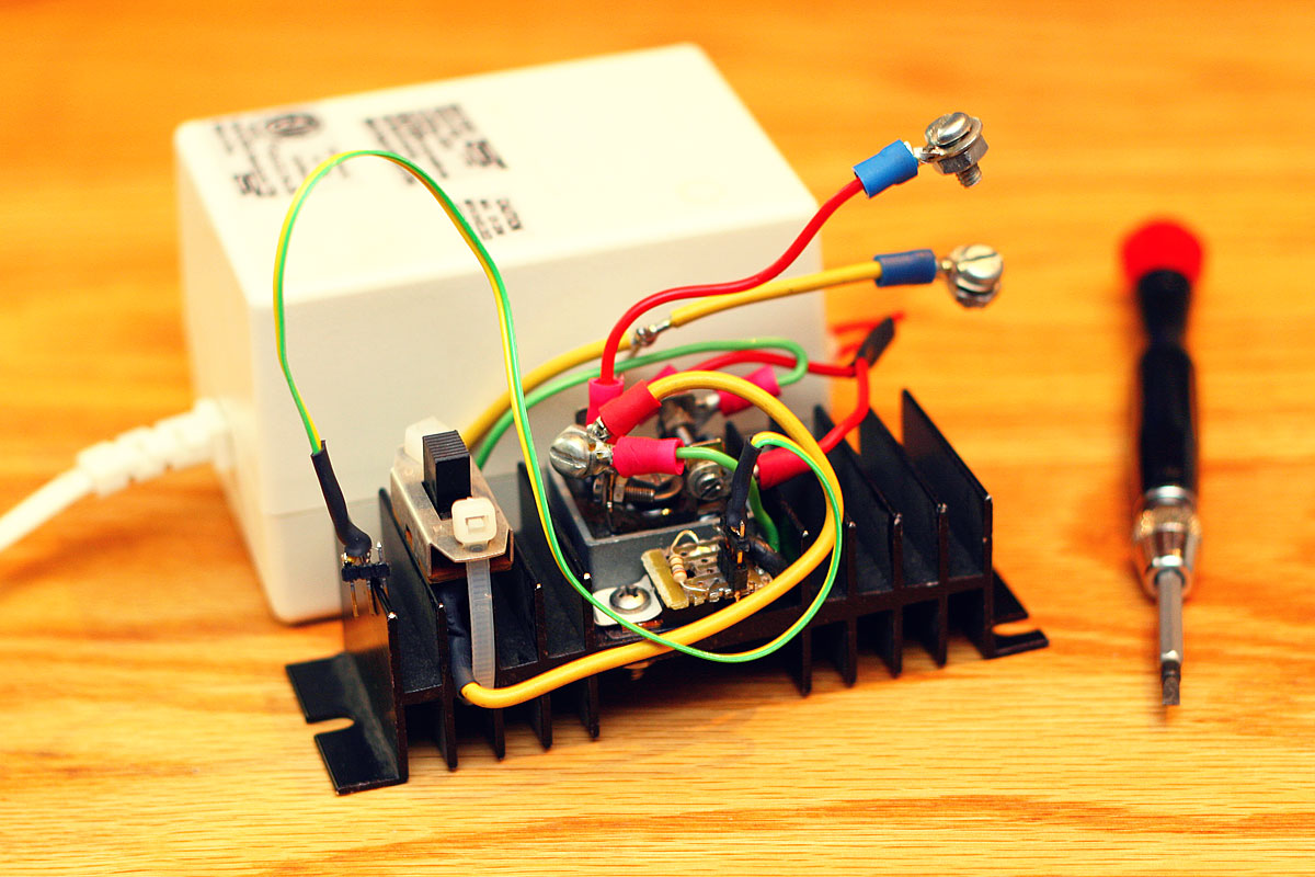
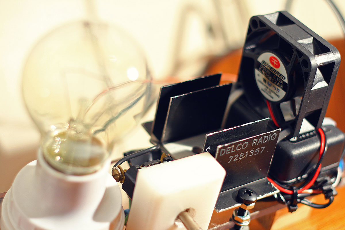
The bridge rectifier and MOSFET were mounted on a small
heat sink and a spare 12V fan was attached above the heat sink for some
cooling. The rest of the electronics were simply component-soldered
directly without the use of a PCB, and turned out to be quite messy, something I will try not to repeat! This mess of wires was conveniently hidden under the heat-sink. Finally, a switch was added to allow the lamps to be (1) Turned off, (2) Turned on continuously and (3) Controlled by the
MOSFET.
This extension was completed on 6th Sept 2011.
[Update]
This circuit is actually dangerous and of poor engineering design because there is
no isolation from the logic to the mains. So I quickly set about making
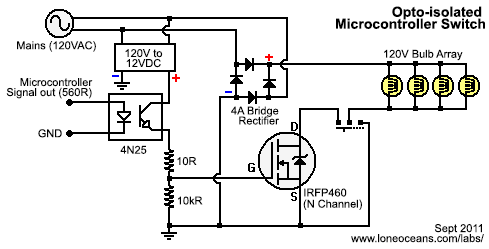
a proper design with opto-isolators.
I quickly realized that mixing mains line and logic was
a poor engineering idea, so I set about making an opto-isolated design.
I'm sure I could have bought one myself since they are dozens of them on
the market, but it's much more satisfying to make it work! The final
design turns out to be just a simple modification but much safer and can
be used as a general purpose mains controller. I knew that I didn't want
to involve any relays for switching (too slow at PWM), so I went
for a rectified mains switch controlled by a power MOSFET as previously.
Use this circuit. Works with 240VAC or anything
in-between as long as you use the right components!
The circuit takes in a signal from the microcontroller which
essentially just needs to light up an LED (remember to put a resistor depending
on what sort of opto you use). Where everything is off, the gate of the
N-channel MOSFET is pulled to ground, so the MOSFET is off and nothing happens.
When the opto-transistor turns on, 12V is switched to the gate which turns
the MOSFET on. we need to rectify the load, so the a bridge rectifier is used. I
also added a switch so I could leave the lights on while still leaving the
device connected. You can use any MOSFET that can handle the voltage and
current. Notice how the microcontroller signals are physically isolated from mains!
At this stage everything is working great and I can now
confidently call this project complete and a success!
[Late 2011 Updates]
I added a new string of 20 ultra-bright green and blue
LEDs under my bed for an aqua-room experience. The contrast and speed
response are far superior to the incandescent bulbs and they look so
very pretty! It can be connected up to any of the 6 frequency bands but
bass still looks the best :-).
It has been just about 6 years since I started on this
project! How time flies indeed. Recently I dug up this project in my
'box of old projects', dusted it off, and plugged it in. To my surprise,
everything was still working just fine... except for two LEDs which were
not lit - one of the left-most white LEDs was no longer lighting up
(perhaps due to a disconnected wire inside?.. the LED was still
functioning) and the Red LED had suffered some sort of accident and was also dead
(the lens had come out and the die itself appeared to be damaged).
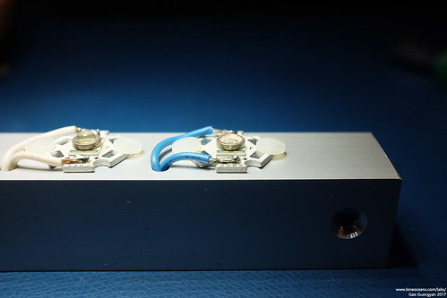
Subsequently, I also found out that the plastic domes of the LEDs were
loose, such as the blue one below which fell off!
So I thought it would be a good time to replace some of
the LEDs (more colours!), and to also tidy up the internals a little
bit. Since 2011, I've also gained a lot more electronics experience and
knew I could implement this in a much better way. However I decided that
my focus was not to do a complete revamp of the project, but rather to do
just a little minor maintenance and upkeep.
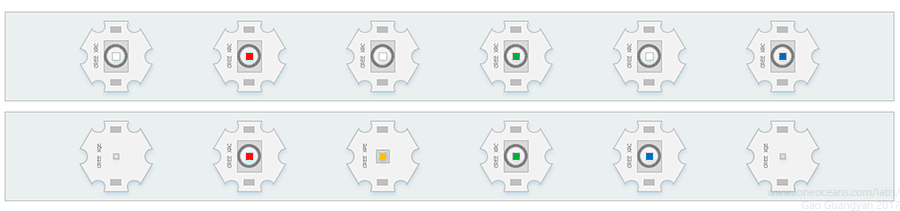
Above shows the general design of my current LED bar
(top drawing).
Having more experience now, I quickly
identified that the LEDs I had used were in
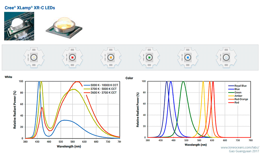
fact from the CREE XR-C line of LEDs. Since 2011, LED technology has
come a long way. But when the XR-C LEDs were
first announced in 2008, they were pretty
groundbreaking indeed. Now if you recall, I planned to have yellow and
purple gels fitted over two of the 3 white LEDs to make a nice spectrum
of colors. However I never got around to doing it, and wound up with a
simple arrangement of 3 alternating white LEDs with R, G and B LEDs.
Now with the left-most two LEDs not working, I thought
it would be a good idea to replace and rearrange the LEDs. My first idea was to replace the
damaged Red
XR-C LED, and substitute three of the white LEDs with an Amber one,
one Warm white LED and one Cool white LED.
After some study (at time of writing), it turns out that the XR-C LEDs are starting to get
phased out and are starting to be replaced with more advanced ones which are much more
efficient (even though they are a lot smaller). However I still wanted to
keep each LED to be on the same 20mm 'star' heatsink to keep the look
tidy. After searching a little online, I found some XR-C LEDs available,
but also found some pre-populated and newer
XQE and
XPE LEDs on the same 20mm star-board in 2 colours of white as well
as amber. The second drawing above shows what it would look like -
slightly odd with the new LED discretes being so much smaller!
Colour
White
Red
Green
Blue
Warm
Cool
Amber
Amber
Warm
Type
XRC
XRC
XRC
XRC
XQE
XQE
XPE
XRC
XRC
Project
Replaced
Replaced
Replaced
Replaced
2017
2017
2017
2017
2017
Wavelength
~6500K
625nm
530nm
470nm
2700K
6500K
595nm
593nm
3000K
V_fwd
3.5
2.2
3.7
3.5
2.9
2.9
2.3
2.2
3.5
I_fwd
350mA
350mA
350mA
350mA
350mA
350mA
350mA
350mA
350mA
Brightness
56.8-87.4lm 80.6lm
23.5 - 39.8lm
39.8-51.7lm
13.9-18.1lm
109lm
126lm
80.6lm
23.5 - 39.8lm
45.7-67.2lm 51.7lm
Resistor Required (ohms)
4.285714286
8
3.714285714
4.285714286
6
6
7.714285714
8
4.285714286
To get a better idea on their brightness, I created a
small chart with luminosity values when driven at their nominal 350mA
I_fwd. Notice how the XQE and XPE LEDs are so much more efficient than
their old XRC counterparts, as well as coming in much smaller packages -
e.g. the XQE comes in a small 1.6x1.6mm package and the XPE in a 3.5mm
package, while the XRC is a 7 x 9mm package. Note that the brightness is given as ranges for some of the old LEDs since I
have no idea which bin of LEDs were used - those LEDs were originally bought from Dealextreme
and came already mounted on the heatsink.
Just when I was about to proceed with this unusual
mixed-LED arrangement, I noticed that some of the other LEDs were..
starting to fall apart! Specifically, the plastic dome of the LEDs were
starting to come loose from their substrate. I did a little more
searching and found that Mouser Electronics still stocked some bare XR-C
LED dies, so eventually I decided to scrap the original plan of mixed
LEDs and to just go with all XRC-LEDs to maintain a consistent aesthetic
look!
Drawing of 2017 update of LED bar using new XR-C LEDs including a
replaced red, new amber, and warm / cool white LEDs. Graphs and photos
by Cree.
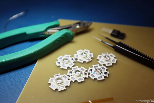
So I decided - a complete replacement of all the LEDs
from their original heat-sinks!
This would mean completely desoldering all the old LED discretes from
their heatsink, and reflowing all new LEDs to the original heatsink
bases. This would also allow me to replace the failing LEDs, and to choose
specific LED bins of the highest efficiency. I settled on using a warm
white and cool white LED for the bass and highest frequency, and then
Red, Amber, Green and Blue for the others. The result is what I have
depicted in the drawing above.
Colour
Warm
Red
Amber
Green
Blue
Cool
Wavelength
2700K
625nm
593nm
530nm
470nm
~6500K
V_fwd (V)
3.5
2.2
2.2
3.7
3.5
3.5
I_fwd (mA)
350
350
350
350
350
350
Brightness (lm)
51.7
39.8
39.8
51.7
18.1
80.6
Resistor (ohms)
4.29
8.0
8.0
3.71
4.29
4.29
I realized this would
also be a nice homage to the Cree XR-C line, considering that it used
the highest and lowest colour temperature of white LEDs, and all the
colour LEDs except the Royal Blue one (too close to blue and looks like
a 'UV LED') and the
Red-Orange one (too close to Red and Amber). I placed an order
from Mouser electronics for the new LEDs.
06 Feb
2017
Light Bar Rebuild
With the new design complete and components arrived, I
started working on rebuilding the Light Bar.
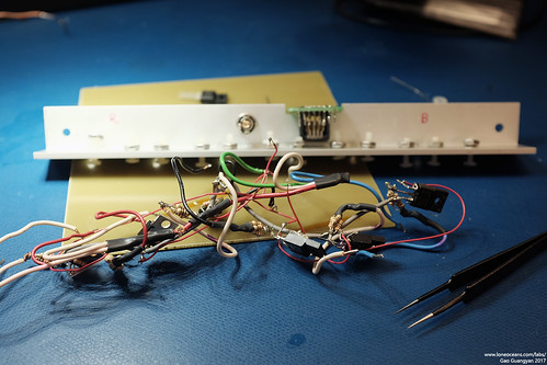
The original light bar was very packed inside and
generally poorly constructed, but opening it up did give me good
memories of the time I was in MITERs putting it together. First thing to
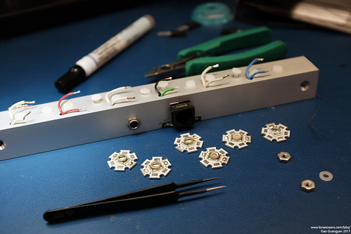
do was to remove the LEDs.
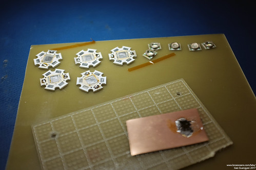
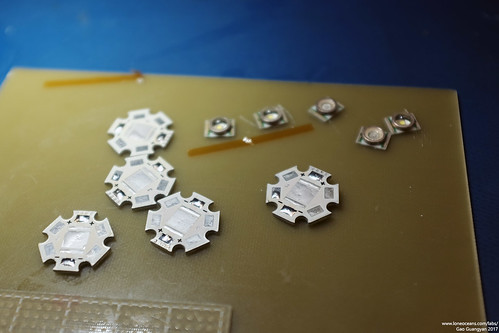
I desoldered all the wires from
the LED assemblies and started the LED replacement process. Using a powerful Metcal soldering iron
with a large wide tip, I heated up the each LED-heatsink package by placing it
on a copper pad, desoldered the old discrete packages, cleaned up the
heatsinks, and then soldered
the new dies back on via reflow. The good thing about choosing new LED dies was
that I was now able to use the specific LED from the brightest bin
available in stock, and the final LED brightness is bolded in the table
above (e.g. the warm white XR-C LED was available in 45.7 to 67.2lm at
350mA drive, but the brightest one in stock was a 51.7lm one and is the
one I used).
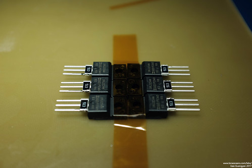
Because replacing the LEDs and the damaged FET would mean desoldering a
significant portion of the build, I decided to re-do the entire
electronics inside and make it a little tidier than before. I also took
the opportunity to replace all the FETs (including one damaged one) with
better newer ones.
Previously I had FQP30N06L MOSFETs (including some IRFIZ34NPbF), but
replaced them with slightly newer IRLIZ34NPbF, which offer essentially
the same of better characteristics in R_ds_on and gate charge, while
having an even lower threshold gate voltage and hopefully have slightly
better performance. The IRLIZ34 FETs also come in a nice isolated tab
TO220 package which allowed me to mount it directly onto the aluminium
superstructure.
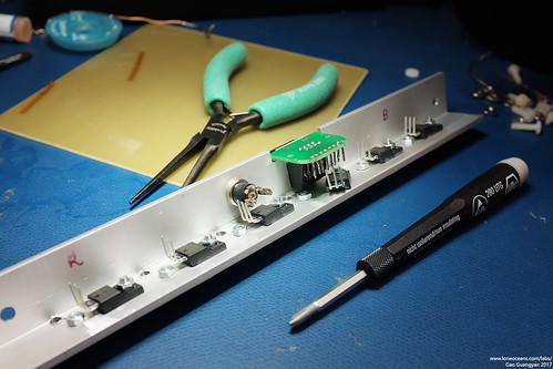
The only problem with the isolated-tab was that the
mounting holes were a little smaller than the regular TO220 packages, so
I had to replace the nylon screws I used. Instead, I switched to
stronger metal M3 screws with nylon washers to prevent shorting out the
+ and - terminals of the heatsink. This worked out very nicely and is a
little more robust and allowed better clamping force since the aluminium
superstructure also acts as the heatsink.
I also replaced the resistor bunches with single 2W 8.2R
or 4.7R resistors (8.2 for the red and amber LEDs) to keep things a
little tidier and also to add a little more robustness (resistors are
fuse and flame-proof metal-oxide types).
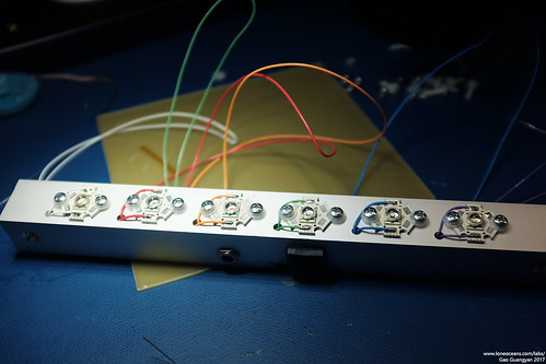
Like previously, I also tried my best to use proper
colour coded wires to wire to the LEDs and they turned out to look
great! Whenever possible all connections were done with 24AWG Teflon-coated
multi-stranded wire. Finally, I connected pin (1?) of the Ethernet
socket to the 5V rail. This will provide the main 5V power which will
drive the down-level ATMega328p MCU, and will remove the need to use
another USB cable to power the logic.
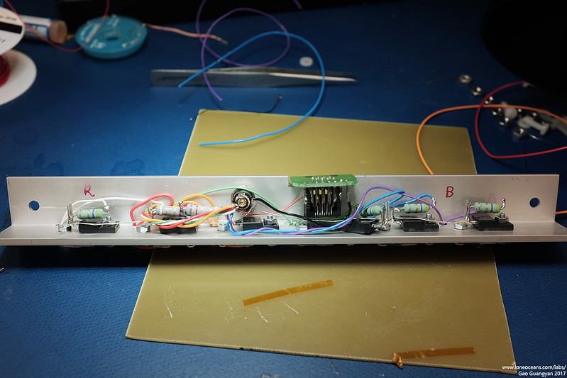
The result is a slightly tidier internal setup with less
likely-hood of shorting out and will hopefully remain quite robust. The
Gate and Source for the FETs were also connected via 51kR SMD resistors
as a default pull-down.
With all that done, I put the assembly back together.
Behold, the new updated Light-Bar! :-)
Updated Light-to-Music Response (2017)
As part of my 2017 update, I also wanted to improve the
performance of the light bar since there was noticeable latency between the audio and the
light. Most of this was likely due to the 'contrast curve' overhead of
the heavy conversion done for each ADC read value.
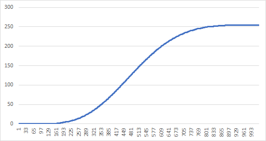
The computed brightness with which to pulse the LED at
(0 to 255) was previously computed as = (1.57sin(1.57sin(input)))^5, where input
was the ADC read value 0 to 1023. This provides a nice curve which looks
like the above. However, using a sin function twice together with a
power 5 was very computationally intensive, so instead I pre-computed
the values with a script and simply created a large look-up table.
The result is a very clean, very quick look-up, and
improved performance dramatically.
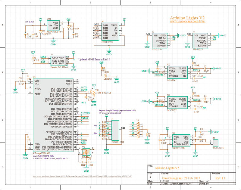
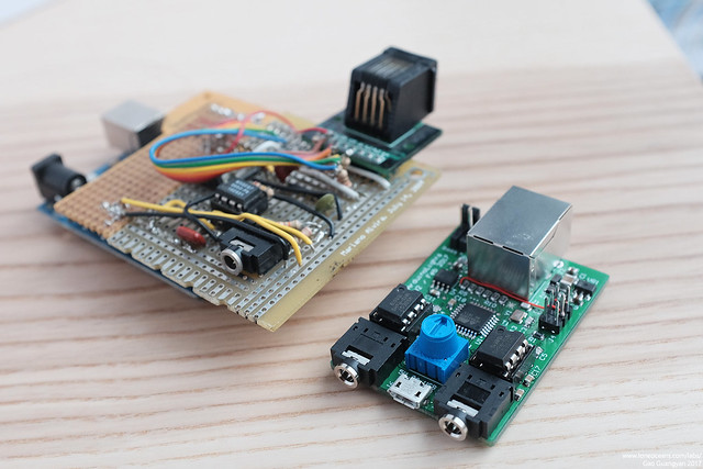
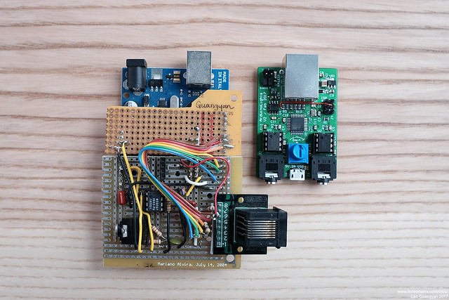
New integrated PCB (2017)
There were many limitations with the original hardware,
mostly the fact that it required an external power supply via USB to
power the Arduino board, that the board was fairly large and finicky,
and that it required an audio stereo splitter which I frequently
misplaced. It was also cobbled together out of two perf-boards and I was
constantly worried about the through-hole parts falling apart. So I
decided to spin the entire thing as a new small circuit board.
I came up with a list of improved and additional features to be
implemented:
- On board 4.5V LDO regulator for core logic from 5V
in
- Integrated Atmel ATMega328p running the same core code as the V1
version
- Dual MSGEQ7 for left and right channel sampling (previously only
sampled Left)
- Dual stereo jacks for Audio In and Out (in parallel)
- Additional dedicated 'bass FET driver' output with resistor
- Uses 5V power from a 2A 5V micro-USB source
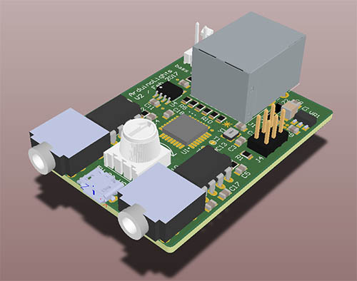
With this in mind, I quickly created a schematic and did
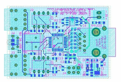
a quick layout on a small 2-layer PCB.
This came together fairly quickly
since it was essentially the same as the original design, but with a few
added features. I managed to fit everything on a small 55 x 40mm board.
Here is how it looked like after layout - fairly straightforward and too
just an afternoon to do.
With the design done, I sent it out for fabrication! The boards arrived and I quickly soldered one up, and I
was quite happy with the way it all turned out! Have a look:
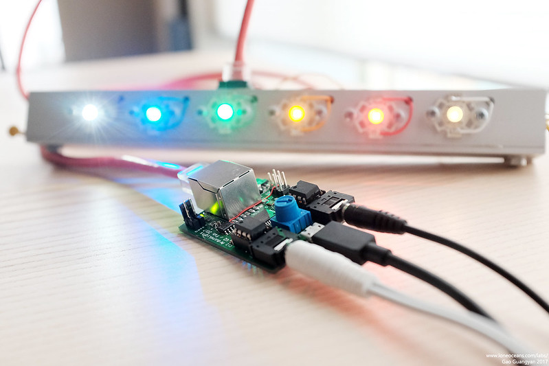
The overall design simplifies things greatly! The first
thing I wanted to do was to reduce the wires going up to the light-bar.
Previously it took 5V from a DC wall-wart power supply, and required the
Ethernet cable for the signals, as well as a 3rd USB power supply for
the Arduino board. Now the entire system is powered by a single 5V 2A
micro-USB power supply which is small and commonly available! Two out of
the 8 wires are also used to supply power to the light bar from the new
board.
I also added two 3.5mm stereo receptacles to the board which allow
one to be plugged into the source via an aux cable, and one to be
plugged to a speaker system.
The original system simply used one MSGEQ7 to sample
only the left channel - this time I placed two MSGEQ7s on board, one
sampling the left and one sampling the right channel. This is fed into
an ATMega328PB, which was also updated with new firmware to optimize the
contrast curve processing speed to reduce latency as much as possible.
In addition, the moving-average system was removed and replaced instead
with a physical gain knob for quick on-the-fly adjustment.
Finally, some debug LEDs were added on the back,
mirroring the output of the system to the light-bar, and a robust
push-pull FET driver was also added and broken out via a 2-pin header
for driving another system synced to the bass notes if desired. I did
found a small mistake I made during the routing for one of the
programming pins, but fortunately that was a very simple fix with the
red wire you see above.
Above shows some photos comparing it was the original
board above. You can see how compact and integrated the new design is
:-).
Finally the entire system comes together!
It works great and with the new firmware, definitely had
an observable improvement in latency.
Conclusion (2017)
I
t's nice being able to come back to a project
after so many years, and updating it using the new skills I've learned, but
yet keeping true to the original design. I kept the
same LEDs and design as the original light bar, but improved the
internals. The main driver is now different, but uses the same core
code, and tidies things up significantly. It was nostalgic looking back at
literally my first serious project with a microcontroller and I'm happy
to see how it has evolved to it's new form. :-)
Hopefully this new musical light bar will see much use in the future,
though I'm already thinking of the next revision with all LEDs and
controller integrated on a single PCB! This will remove the need for
building a light bar, and be truly fully integrated!
Until next time, thanks for following this project and
making your way here till the end!
Component Cost
2011 Project:
(this includes a pile of spare components not used in the actual project,
so it's more for my record):
- Arduino Uno (after discount) - $19.95
-
Sparkfun Order for MSGEQ7 and various MOSFETs - $30.31
-
Dealextreme Order for LEDs and other components - $38.18
2017 Improvements:
- Total additional cost for
new R,A,G,B,wW and cW XR-C LEDs, MOSFETs and resistors from Mouser Electronics
(before tax and shipping) - $32.44
Back to main page
(c) Gao Guangyan 2025
Contact: loneoceans [at] gmail [dot] com
Loneoceans Laboratories. Copyright (c) 2003 - 2025 Gao Guangyan, All
Rights Reserved. Design 3.
Removal of any material from this site without permission is strictly
prohibited and will result in infringement of copyright laws.
Disclaimer: Projects and experiments listed here are dangerous and should
not be attempted.
www.loneoceans.com/labs/
... page generated in 0.00013 seconds


 This project was motivated by a desire
to light up my dorm room in college. The common dorm room usually comes
with a little fluorescent lamp in the middle of the room providing general illumination, but just barely. My room in Next House was no exception. Yet the idea of buying a little table lamp was unappealing. Earlier on in the semester, I had acquired a set of three 20W Halogen lamps and they added much warmth and comfort (everybody loves
Halogens!). Still I wanted a bit more dynamism and colour - not simply
to install additional lights, but also to bring a little more flavour and piazza to my room. Afterall, I was
in a tech school.
This project was motivated by a desire
to light up my dorm room in college. The common dorm room usually comes
with a little fluorescent lamp in the middle of the room providing general illumination, but just barely. My room in Next House was no exception. Yet the idea of buying a little table lamp was unappealing. Earlier on in the semester, I had acquired a set of three 20W Halogen lamps and they added much warmth and comfort (everybody loves
Halogens!). Still I wanted a bit more dynamism and colour - not simply
to install additional lights, but also to bring a little more flavour and piazza to my room. Afterall, I was
in a tech school.