31 x 8.625 in, SKM400 Semikron bridge,
55kHz,
2.5m+ sparks
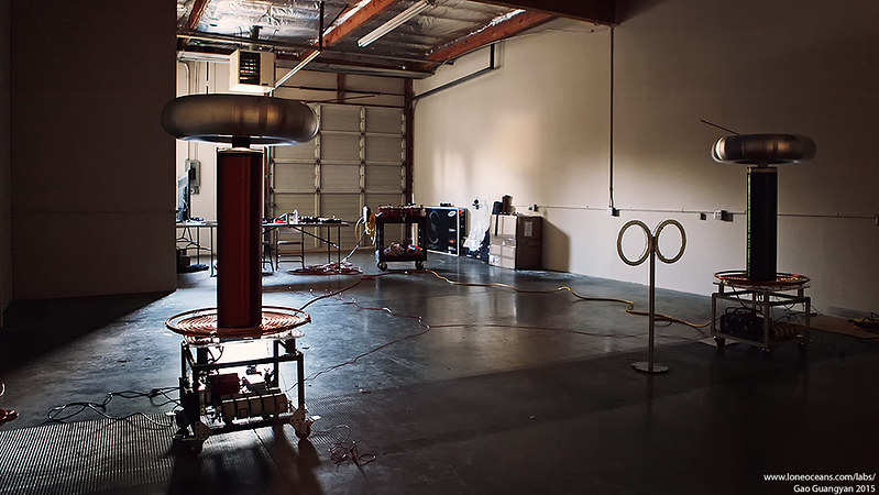
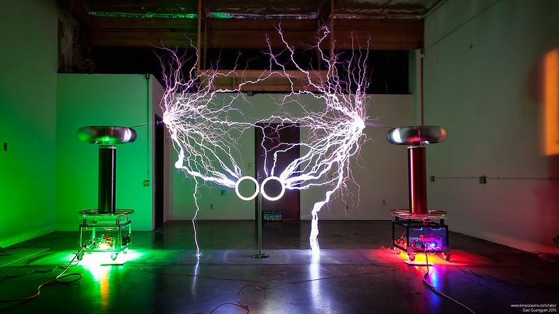
Model 82 - Musical Tesla Coil Twins (2015)
The Model 82 Tesla Coil platform builds upon the work of my
DRSSTC 3and was designed from the ground up with the primary purpose of
developing a powerful and compact twin museum-grade electronic
Tesla Coils. These coils have been developed around modern IGBT
technology, and at time of development, represents one of the largest and
most powerful musical Tesla Coil systems in the South East Asia region.
The Model 82 coil system is so named, being the 2nd 8-inch secondary
diameter platform of my design. See my Model 81
Tesla Coil page.
Twin Model 82 Musical Tesla Coils with myself :-)
This platform was developed to be compact, reliable and robust, with an
intended electrical discharge of easily over 2 meters each coil despite
each coil having only a 79cm secondary winding length. The Model 82
project was designed in the early months of 2015, with the first twin
pair of coils completed in early April 2015 as part of a commissioned
project and their performance surpassed their designed goals with ~9
feet spark length acheived.
Depending on operational characteristics, the average operating power of
each coil ranges from about 1 to 8kW RMS, with a maximum pulse operating
power exceeding 550kW. These coils are controlled via my custom MIDI
synthesizer which supports playback from a computer or a MIDI device
such as a keyboard, supporting up to two channels and two notes of
polyphony. The coils can also be operated in a 'stand-alone' mode.
Control is done remotely and safely via a fiber-optic cable sending
signals from the controller to the Tesla Coils.
Design Specifications (April 2015)
- Full Bridge inverter, set to a
800 Apk current limit for robustness
- 2kV 1uF x 2 Aerovox snubber capacitors
- FR4 Fiberglass and Aluminium laminated bus (1/16")
- 375nF 10kV Tank Capacitor
- UD2.7C Driver with Primary Feedback and Phase Lead for ZVS
- Flat Spiral Primary, 1/4" Copper Tubing
- 31x 8.625" Secondary
- 30" x 7" Spun Aluminium Toroid
- Designed for 240VAC input max for +-678VDC on the bus
- In excess of 2.5m+ spark output
Geometry
CAD Modeling
Development of the Model 82 coil was done completely in CAD
(Computer Aided Design) to ensure proper dimensioning and to ensure that
everything would fit in place. This also allowed for me to have a
'preview' of the complete coil, and also aided in actual construction
since all dimensions were already determined. Electrical simulations
were conducted as well.
Primary and Secondary Coil
The primary coil was constructed using standard 3/8"
flexible copper tubing. For quick construction, supports were laser cut
from 12mm acrylic sheets, and the entire setup sits on a thick acrylic
table. The primary supports were designed in such a way to allow the
copper tubing to be press-fit into place with not additional clamps or
fasteners required.
The result is a strong and tidy primary coil, whilst
being simple to construct. Unfortunately the low melting point of
acrylic limits both the maximum possible current and duration before
they melt! However in practice, the coils have been run at full power
for several minutes and still remain cool enough for the supports.
The secondary coil was made using 8" diameter white PVC
pipe, each sanded and cleaned before winding. The winding aspect ratio
was arbitrarily chosen to be about 1:3.6 simply to maximize the length
of pipe which could be fit onto a particular lathe I was using. Winding
the coil on the lathe allowed me to automate the process, and each coil
took less than an hour from start to finish. The coils were then coated with
polyurethane varnish for protection.
The coil can be easily disassembled into 3 main parts
for easy transportation - the Toroid, the secondary coil, and the rest
of the coil.
Frame
All of the electronics and and support for the coil was
constructed to fit in a frame measuring around 18" x 18" x 10", made
from 80-20 aluminium framing. This allows extremely quick construction
while being very robust and strong.
Side panels are constructed from clear acrylic with
laser-cut mounting holes for power socket, switches and indictor lights.
The base is made from stronger polycarbonate. The entire setup sits on 3"
locking rubber wheels for easy transportation. Note that (not shown) care was also taken to
ensure discreet electrical breaks in the 'loops' created by the framing
to reduce inductive losses from the primary coil during operation.
Inverter and Power Electronics
Inverter and IGBTs
The heart of the Model 82 Tesla Coil is the
power inverter made out of the best modern IGBTs on the market
today. Each coil contains a H-bridge comprising of two
high-speed Semikron IGBT power modules, each capable of 300A
hard-switched at 800V. However these transistors can be* operated
at significantly higher pulse power capability by employing
predictive switching allowing for resonant zero-current
switching. With a low duty cycle and a robust gate drive, these
IGBTs can be driven up to 1000Apk+ at 600V at up to 70kHz.
The Model 82 Tesla Coil system uses 62mm SEMITRANS 3 series IGBTs from Semikron.
Careful
thermal analysis was conducted to ensure that the junction temperature
not be exceeded. Indeed significant over-current can cause die delamination and damage the chip metallization, causing premature
failure.
The H-bridge was specifically designed with an ultra-low
inductance layout via a custom laminated bus, machined from aluminium
sheets and
FR-4 fiberglass. This allows the physical location of two high-ripple
current bus capacitors and two 2uF 1kV snubbers
capacitors connected to the inverter in an extremely low inductance
design for the best switching performance and reliability. This combined
with predictive resonant switching leads to near perfect ring-free
resonant
switching. The entire setup is mounted on a large heat-sink cooled via
two 120mm high-speed fans.
Tank Capacitor
Because of the high RMS currents the resonant capacitor
will face, it is imperative to design a resonant capacitor capable of handling this
enormous power.
A total of 10 axial-type cylindrical
GTO snubber capacitors were used, each being 580Vrms and 3.75uF
each. These polypropylene film capacitors are extremely robust, and in
series form a 5.8kV 375nF tank capacitor, more than capable of handling
the high RMS power for the Model 82 coil.
Measurements
Predictive Zero Current Switching
13 Apr 2015
Due to the massive ~1000Apk currents running in the primary
circuits, the Model 82 Tesla Coil system utilizes predictive
switching in the main inverter. In short, a predictive circuit
allows early switching of the main transistors in the inverter.
In this way, the IGBTs are switched a fraction of a second
before zero current crossing. Because the transistors take a
finite amount of time to switch, this allows the transistors to
fully saturate just at the point of zero current crossing. This
results in significantly less dI/dt switching spikes, leading to
extremely clean switching with minimal switching loss.
Scope shots 1 to 4 show increasing phase lead. Magenta = primary
current, Cyan = V_ce, Yellow = V_ge.
Scope shots 1 to 4 show images demonstrating less to more predictive switching. Image 3 is
the critical point near perfect zero current switching. Notice
how 1, 2, and 4 shows ringing on the bridge and gates, which are
mostly absent when tuned just right. The critical part to note
is that Vce drops just before the IGBT turns on.
Low voltage test at 68VDC on the bus, reaching just over 200Apk
operating at just about 60Khz.
Finally, above is a scope shot of the test with the coil
operating just over 200Apk with perfect switching at around
70VDC on the bus. In actual operation the primary circuit will
see a maximum of just less than 1kA, though practically speaking
the circuit may be able to handle up to 1.5kA.
10 Dec 2015
Some scope shots were taken during another tuning at 400A in Dec
2015. The following shows screen shots for the Red Model 82.
Here we see the effects of proper resonant switching resulting
in beautiful clean outputs. Gate resistors are 5.1 ohms.
Results & Performance
Jan - Apr 2015
The Model 82 Tesla Coil twin system was completed in early April
2015 as shown above. Each coil stands over 5 feet tall (>1.5m).
First Light & Preliminary Tests
First light of both coils took place around March 2015 -
both coils performs very well, and both were running at about 200VAC
input from a single 4kW Honda generator which was struggling to keep up!
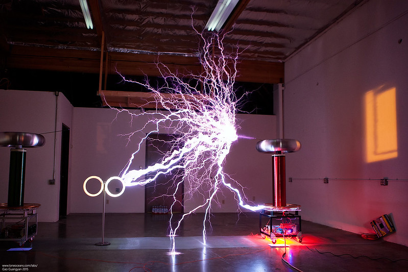
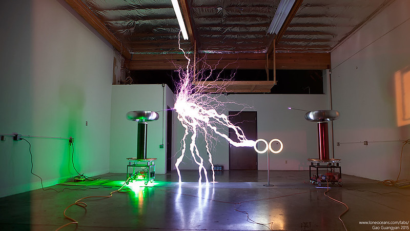
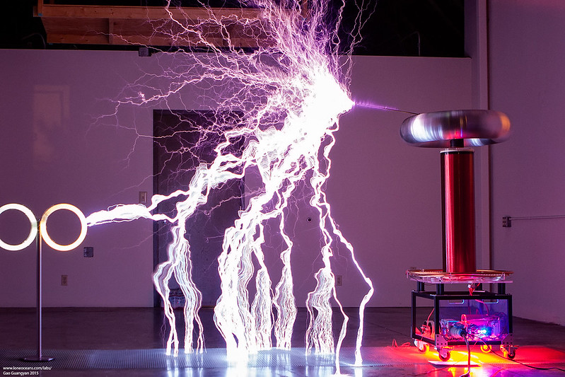
More Results
It's challenging to find a place to run the coils. Regardless, I managed to find a location and the coils were tuned up
further. The results are pretty spectacular. Below shows the coils
running at about 220VAC input from a 30A power line.
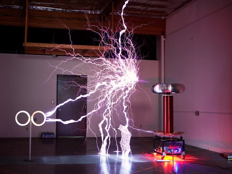
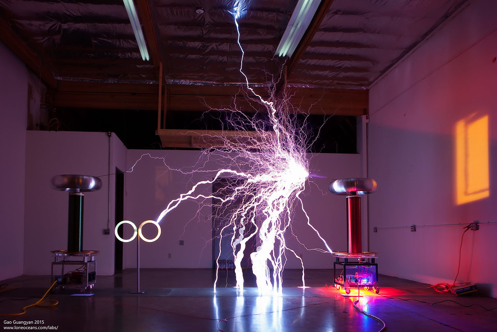
It was difficult to measure the maximum spark length since the
sparks were very much wanting to just hit ground!
A long spark captured in a photo. The gap here is 8.5 feet or
2.6m. Maximum spark length was just about 9 feet at the current
bus voltage (220VAC in) and with OCD set just over 800A.
Videos
Finally some videos of the coils in action!
For more information and for project commissions, please contact
me via my contact information below.
Back to main page
(c) Gao Guangyan 2026
Contact: loneoceans [at] gmail [dot] com
Loneoceans Laboratories. Copyright (c) 2003 - 2026 Gao Guangyan, All
Rights Reserved. Design 3.
Removal of any material from this site without permission is strictly
prohibited and will result in infringement of copyright laws.
Disclaimer: Projects and experiments listed here are dangerous and should
not be attempted.
www.loneoceans.com/labs/
... page generated in 0.00012 seconds