|
|
|
High Voltage Ignition Coil Experiments Introduction So what is an Ignition Coil? An Ignition Coil is an induction coil that converts current from a car battery (12V) into the high-voltage sparks required by spark plugs in a car engine. An Ignition coil is like a high voltage transformer, and like a transformer, contains two windings (primary and secondary) wrapped around a steel/iron core. The ignition coil uses a rod core, instead of the classic transformer design, though I have seen some transformer shaped ignition coils. They still work more or less the same way. All this is placed in some insulation like epoxy or oil. The primary coil has a few turns (connected to the 12V battery), and the secondary coil has many turns (which of course has the HV output). The ignition coil is important as it is needed to make the high voltage output (around 10 - 20kV) for the spark plugs. In older cars, the battery current is periodically interrupted by the contact breaker in the distributor, as the engine runs. However, solid-state switching using chips are now used as they are better and more efficient. So how does an ignition coil work?
As I mentioned previously, an ignition
coil is like a transformer, and works on electromagnetic induction.
When current is applied to the primary coil, a magnetic field is
created. However, when this current is removed, the magnetic filed
collapses and this will induce a current on the
secondary coil creating a high voltage spike. This happens many times
a second creating an apparently continuous spark, which is
passed to the spark gaps. Driver Circuit and set-up
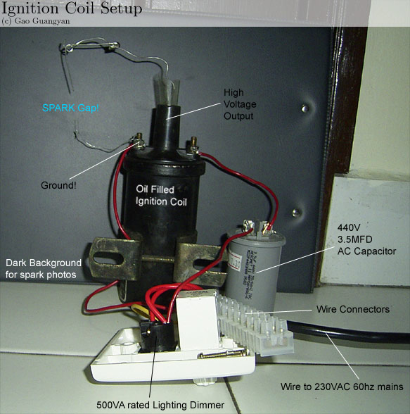
So now you know what an ignition coil does, lets move on to the experiments. An ignition coil is an excellent generator for high voltages. It's also cheap (you can either get them free or very cheaply at your local car mechanic) and durable (meant for long use in cars). There are 2 types, the cylinder oil-filled types (like mine) or squares HEI types. Both will work fine. We need a rising and collapsing electric current through the primary to make HV off the secondary, so lets see how I did it. On the left you can see the simplest of setups. It's extremely easy to make, and it's quite impossible to get things wrong as there are only 3 components. It works off the mains however, and can be extremely lethal. The capacitor can store a fair amount of energy so always remember to discharge it after use. On the right, you can see my simple set-up. I added a dark background to facilitate easier photo taking and spark viewing. The plastic thing on the top is my attempt at preventing arc over from the HV lead to ground. Obviously the output is significantly higher than if run from a car battery (I'm using the mains) so therefore I need better insulation. I haven't obtained high voltage rated cables yet so I'll just have to wait before insulating the whole thing. One option would be to dip the whole thing in oil, but it's kind of messy, so I'll wait till I obtain the suitable materials and properly insulate everything. Here's a diagram of my circuit:
It can't get easier than this. But how does it work? This is what happens. The dimmer contains a device called a triac, which is an electronic switch that gets triggered in sync with the mains frequency. The knob on the dimmer adjusts the timing of the trigger. When the triac triggers, it closes a circuit consisting of the ignition coil primary, the cap, and the AC line. (1) The cap discharges into the ignition coil, then charges again from the line, through the ignition coil, to the opposite polarity. Once the cap is charged the current through it falls to zero which causes the triac to turn off. While the triac is off, the line voltage goes through zero and builds up in the opposite direction. If you have set the dimmer knob correctly (about 50%) the triac fires just as the line reaches its peak in the opposite direction, so the coil gets slammed with the full line voltage, plus the full voltage of the charged cap. On my 240V line, that's something like 680V. (The voltage of the fully charged cap is around 340V, and the peak voltage of the line is around 340V too. The ignition coil gets hit with both voltages in series: 680V.) Return to point (1) and repeat 100 times a second (Please e-mail me if I have made any mistakes or errors in this calculation). I do not have the equipment to measure the current or voltage accurately at this time though. Parts Needed Constructing this circuit is simple. We only need a few components. You can get the ignition coil from your local car repair shop. Just ask them for one, and say you need it for a project. They might give you one for free or at a low cost. Of course don't expect to get a brand new one. It will be a used one and be prepared to wash the grease off. Another alternative is to buy a new one which shouldn't cost much more than $10, unless you're getting a really good one. The dimmer is quite straight forward - your local mart would have it. Go to the lighting section and find a light dimmer. The higher the rating, the better. (500W or above should be fine) You wouldn't want to blow it and go back to buy another one. Finally, the capacitor: You need an AC capacitor of anything from 0.1 microfarads to 20 microfarads (30uf is about the limit for cap size. I don't suggest you try a bigger one..), at any voltage from about 250-600V(depending on your line voltage). They all work, but the bigger the cap, the greater the output power. If the cap is too big, the ignition coil will overheat. If the coil body gets too warm to comfortably hold in your hand, you need a smaller capacitor. Using my 440VAC 3.5 microfarad capacitor, it doesn't even get warm after a long use! The final thing you need are the wires, and connectors. Proper Insulation At these high voltages, insulation is important. There are a few ways to insulate HV out when the high voltage keeps arcing out from the terminal to ground. To have sufficient insulation, you must pay attention to creepage and clearance. Clearance is obvious enough, it is the distance of material between two conductors that will prevent breakdown of the surrounding material, causing some kind of conduction (around 1.1kV per mm). Creepage is due to arcs "tracking" along surfaces to reach their destination. (eg. from the HV terminal to ground, the arc follows the surface of the ignition coil top.) The way to get around this is to increase the distance the arc has to travel. If you look at HV power transmission lines on pylons, you can see that the insulators are ridged all the way down. This is to increase the path length the arc would have to follow, increasing the breakdown voltage. One way is to try placing a piece of HV insulated wire in the HV terminal and then fill the terminal up with epoxy. Another way, is to cut a circle of plastic, protruding about 3cm, fitted over the top of the ignition coil. Holding it in place with a decent sized bead of bathroom silicone sealant all the way around (making sure there are no gaps) will prevent any tracking around. Obviously, if a bit of silicone is missing, it will arc through the hole left. Electricity will tend to take the easiest path. There are many other different driver circuits like 555 timers or transistor circuits, but I am sure the circuit I am using is better, easier and faster to fix together, and there's so little to go wrong. (3 components only..) Also, it does not require expensive power supply units, and is generally, much more powerful than 12V inputs. Now on to my experiments. Experiments with arcs
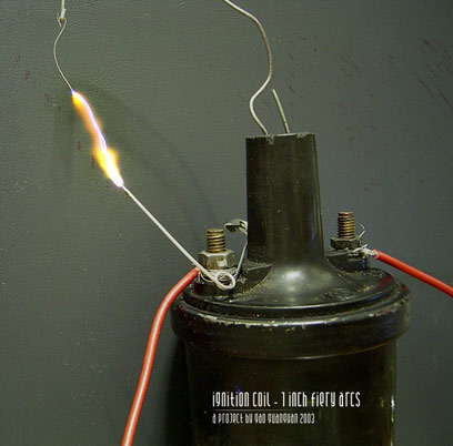
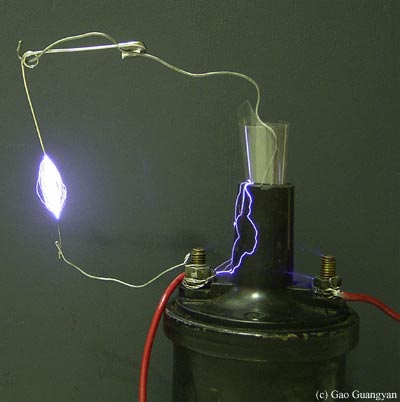
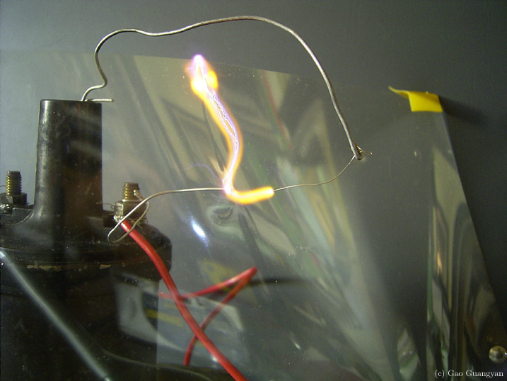
Two different pictures. Lets take a look at the one on the left first. That's a 1 inch hot, fiery arc, made by pulsing a 250V 240uf charged capacitor through the primary. Sure it's only one discharge and it's not continuous arc, but now we know the coil works at least. (tested the coil before I bought the other components for the circuit) After wiring it up with my mains circuit... (second picture) This is a 1/2 second exposure so you can see the multiple arcs. Also notice some arcs creeping along the surface of the coil to ground (proves my lousy temporary insulation doesn't work), and the corona from the other point. Lots of Electro-Magnetic waves are generated and every time I turn it on, the TV display would start to mess up... The voltage generated in clearly very high, possibly over 30kV or more.
New pictures!
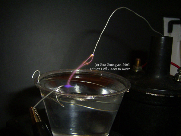
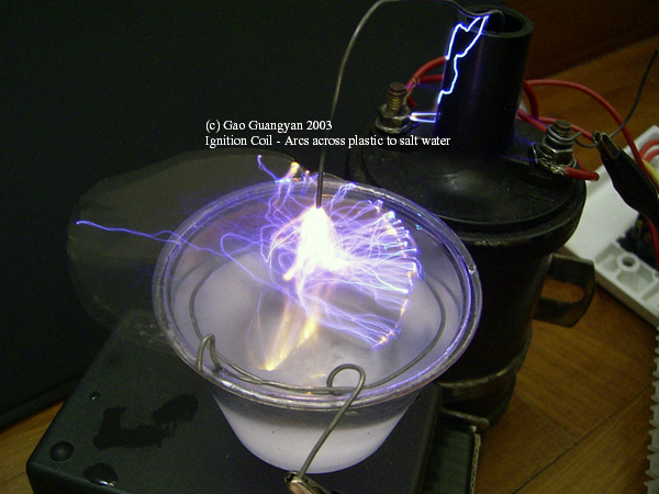
These are new photos not released before! First picture shows a short exposure of an arc arcing to a pool of water. Note the colours and the ripples caused by the arc. The second one is a 1 second exposure of arcs snaking around a plastic sheet to a pool of salt water. Click to enlarge.
More power to the coil! Instead of a 3.5uF capacitor, I upped it with a cheap 250VAC 8uF capacitor. (In case you were wondering, the white stuff is hot glue) The difference is quite obvious. Instead of thin blue arcs, they have changed into fiery hot bright arcs. There is clearly a lot more current in the arcs. Compare this picture with the one above (with the bluish arcs) and see the difference. However, at this levels, the coil gets warm to the touch only after a while. The 3.5uF configuration allowed the coil to stay cool even when run for extended periods of time. I plan to use a higher capacitance capacitor and see what happens... people have driven the coil up to 5000W! Ignition coils are built quite well and they are almost like small versions of Pole-Pig-Transformers/Power Distribution Transformers and can handle quite large amounts of overrating and abuse.
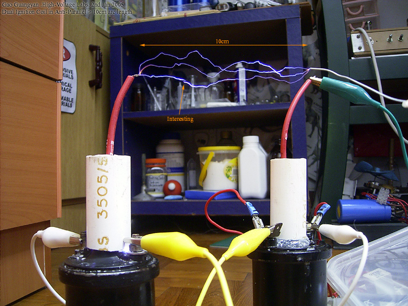
[Updates 2nd Jan 2005, Sunday]
Look at the diagram on the left. I first soldered the 40kV rated wire to the HV output. Then I got a piece of PVC pipe (blue pipe in the diagram) and stuck it over the top of the HV terminal, and sealed the bottom with a generous amount of hot glue (light blue). The tube was then filled with melted candle wax (yellow) and left to cool. I did this to two of my ignition coils. Normal arcing will occur where the blue arcs are in the diagram. Once completed, I plugged one coil in the driver as above (using the 3.5uF cap) and I got amazing results! However there were arc-overs at the bottom of the PVC pipe (indicated by the green lines at the diagram) if I pulled the electrodes apart too much.. looks like the voltage is too high! (which is good :-) )
The photos on the left shows my achievement. The first photo shows arcing at 6-7cm distance. The second photo shows the 10cm arcs. There is a arc which seems unconnected in the photo. I'm not sure what causes it but if anyone has an explanation, feel free to contact me and I'll update this. Click photos to enlarge. In the future I might get two better coils and enhance my driver circuit to achieve even greater spark length. I can enclose everything in a clear acrylic container and fill it with good transformer oil. This will stop the arcing over and insulation problems once and for all! Other Experiments with the Ignition Coil Experiment with 'Plasma Globes'
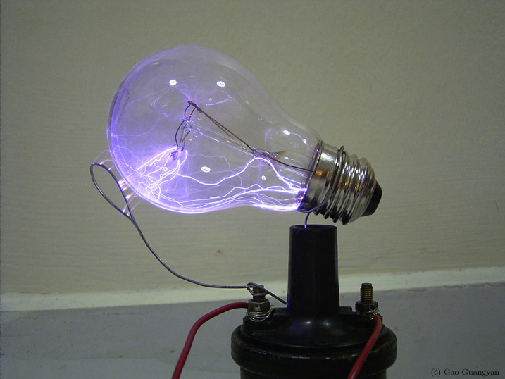
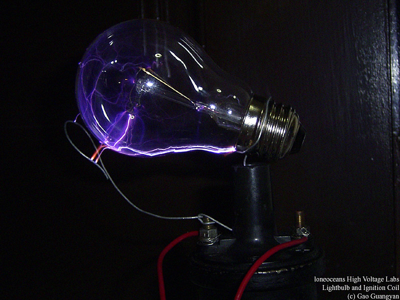
After my experiments with flyback driven plasma globes, I decided to give a try by hooking up a light bulb to the HV output. It won't work like a plasma globe due to the low frequency, but I expected spectacular results. The pictures have proved me right! This is a loneoceans must see picture! (click the thumbnails now) There are arcs inside and outside (the surface) of the bulb. Also notice the arcs from ground (the loop of wire) to the bulb. In real life, the arcs are much more purple, most probably due to the low-pressured nitrogen in the bulb. A video is available for download. (Scroll down) Experiment with the Jacob's Ladder
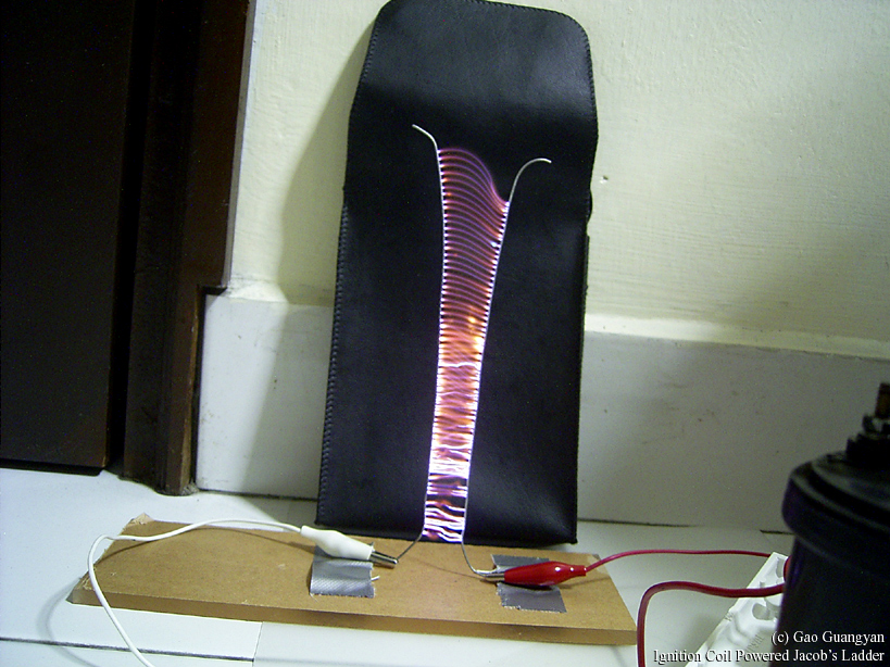
On the left you can see a 1 second exposure of the the jacob's ladder. The increased power I get from this coil allows me to build a much bigger and taller jacob's ladder than the flyback driven one. This picture shows the arcs starting from the bottom and moving up to the top, extinguishing, and starting from the bottom, just like those science-fic movies in the past, just that mine is smaller. It makes a loud bzzzzz sound as it goes up and after a short use. Ozone production is higher and the wires get much hotter than the flyback driven ladder. Compare with my flyback driven one and you can see how much nicer this one is :) Just look at those arcs.. If you coat the wires with salt, the result is a bright yellow arc. It has a plastic base, with two wires duct tapped on it, and bended in a shape of a "V". One side is high voltage and the other is ground. The jacob's ladder is very much affected by even the smallest wind, and precautions had to be taken to make sure the wind didn't blow it out before reaching the top of the 'ladder'. Videos! Ignition Coil in Action and with bulb attached: ignition.wmv (799kb) Updates: 1st
Feb 2004, 7th June 2004 |

 More
updates! I finally got around to do what I wanted to do. As you can
see from the photos above, the the HV insulator is obviously
inadequate and the HV arcs over. This is seriously limiting my maximum
arc length. I bought some 40kV wire (like those in flyback
transformers) some time ago for $2 per meter and I haven't got around
to using it yet. I also went out and bought some tea-light candles
yesterday.
More
updates! I finally got around to do what I wanted to do. As you can
see from the photos above, the the HV insulator is obviously
inadequate and the HV arcs over. This is seriously limiting my maximum
arc length. I bought some 40kV wire (like those in flyback
transformers) some time ago for $2 per meter and I haven't got around
to using it yet. I also went out and bought some tea-light candles
yesterday.