loneoceans labs | UD2 Pre-charge Add-On Board (temporary placeholder page)
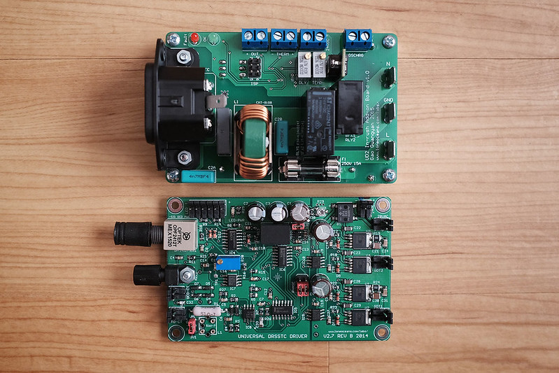
The UD2 add-on board (top) pictured with the UD2.7C Tesla coil driver (bottom)
The UD2 Pre-charge board is a simple no-frills add-on board designed specifically as a companion with the UD2.7 Tesla Coil Driver for small to medium sized solid-state coils. Measuring at 2.4 x 3.7", it has the exact same footprint and mounting holes as the UD2.7 driver, which allows them to be stacked and mounted in a very compact configuration, allowing plug-and-play operation for your Tesla Coil.
[Update May 2016 - This board is now sold out and no additional boards are planned for fabrication, and I will not be able to provide future support for this board. Boards have been released as part of the Creative Commons CC BY-NC 4.0 here.]
What does this board do?
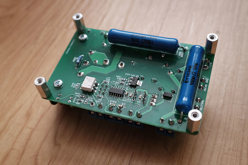
Most solid state coils which use the UD2 driver invariably require the use of a large bus capacitor. This capacitor (typically several thousands of uF) looks like a short across the mains during first turn on, which can cause fuse blows / breaker trips. The solution is typically to use a large heavy variable transformer and ramping up the voltage slowly, or a separate complicated pre-charge circuit such as a phase angle controller or electronic variac to limit in-rush current. This board provides a simple, reliable solution which pre-charges the bus cap via a special ceramic composititon150R power resistor (this was chosen over NTCs for a variety of reasons) for an adjustable time (couple of seconds), and then bypasses it once the capacitor is charged, preventing in-rush surge current.
In addition, the board allows for safe and automatic bus-cap discharge once power is turned off, by shorting the bus caps across a 1kR power resistor, thus allowing the circuit to be safe within seconds instead of tens of minutes. Furthermore, the board includes a common IEC power socket input, basic EMI Filtering, a standard 5x20mm Fuse, and also adds a thermal-cut-off capability via an external thermistor, and plugs into the UD2.7's UVLO trip allowing the driver to be turned off in such a fault condition. The result is a nice, simple companion to the UD2 board.
For more information about the UD2.7, please see http://loneoceans.com/labs/ud27/.
The add-on board features the following functions:
Version 1.0, as of Mar 2016 - Verified working
These boards are currently being offered as a complete, programmed and populated board each as pictured:
The listed prices are for a single populated and completed board.
Board only uses high quality brand-name components such as Murata switching regulators, Fujitsu relays and special Ohmite carbon composition pre-charge /discharge resistors specifically designed to absorb the large energy dissipation while charging and discharging the capacitor bank. The result is an increased total cost of the Bill of Materials, but also significantly increases reliability of the board for long-term operation.
Populated boards come pre-adjusted and tested with the following settings:
This board was designed as a personal project and may not work with your set-up. Please note this board was designed solely as a personal hobby board, and interfaces with deadly mains / line voltages! I make no claims that the board satisfies any UL, CE or any electrical standards. You will bear all responsibility for using this board correctly and safely in your project with good engineering practices.
Shipping is from the USA to anywhere around the world (not included but usually relatively cheap) starting at $7.50 for USPS Priority Flat Rate and starting at ~$15 for international orders. All prices are in USD
Contact loneoceans [at] g mail [dot] com for enquiries.
There are two adjustable resistors on the board, corresponding to a pre-charge bypass timer, and the other corresponding to the temperature trip setting.
Bypass Timer
For simplicity and reliability, pre-charge is conducted via a 150R power resistor. When 24VDC power (usually from a UD2) is applied to the board, the 150R charging resistor is bypassed with a 16A relay after a set delay time. This potentiometer is labeled (RLY) on the silkscreen, and has a corresponding tap-point for setting labeled "< R" This can be adjusted from 0 to 5V, and the corresponding delay is from 0 to 10 seconds.
Delay (seconds) = V_rly(Volts) x 2
The 150R resistor limits the maximum charging current to 2.25A with 240VAC
input. It is possible to calculate the appropriate delay by using a simple 3RC
formula. For example, with a 5600uF bus cap, the 3RC value = 2.52 seconds. Hence
the potentiometer can be adjusted to be at least 2.52 / 2 = 1.26V or higher.
Temperature Trip
The add-on board adds a simple (and optional) temperature cut-off functionality, and is designed to tie into the UVLO pull-down line on the UD2.7. Temperature sensing is done via a 50kR Epcos TDK B57861S0503H040 Thermistor. It is important to use this thermistor since the temperature profile is programmed as a look-up table into the controller and works specifically with this thermistor. That said, in general most 50kR thermistors (corresponding to 50kR at 25C) of similar characteristics can be used. The look-up table is as follows:
| Volts | Temp (C) | Volts | Temp (C) | Volts | Temp (C) |
| 0.0 | 155.0 | 1.7 | 43.2 | 3.4 | 8.4 |
| 0.1 | 155.0 | 1.8 | 40.7 | 3.5 | 6.4 |
| 0.2 | 136.3 | 1.9 | 38.5 | 3.6 | 4.3 |
| 0.3 | 114.3 | 2.0 | 36.3 | 3.7 | 2.1 |
| 0.4 | 101.7 | 2.1 | 34.1 | 3.8 | -0.1 |
| 0.5 | 91.8 | 2.2 | 32.0 | 3.9 | -2.4 |
| 0.6 | 84.4 | 2.3 | 29.9 | 4.0 | -4.8 |
| 0.7 | 78.4 | 2.4 | 28.0 | 4.1 | -7.3 |
| 0.8 | 73.1 | 2.5 | 26.0 | 4.2 | -10.0 |
| 0.9 | 68.5 | 2.6 | 24.1 | 4.3 | -13.0 |
| 1.0 | 64.3 | 2.7 | 22.1 | 4.4 | -16.4 |
| 1.1 | 60.6 | 2.8 | 20.2 | 4.5 | -19.8 |
| 1.2 | 57.1 | 2.9 | 18.2 | 4.6 | -24.1 |
| 1.3 | 54.0 | 3.0 | 16.3 | 4.7 | -29.3 |
| 1.4 | 51.0 | 3.1 | 14.3 | 4.8 | -35.4 |
| 1.5 | 48.3 | 3.2 | 12.4 | 4.9 | -44.5 |
| 1.6 | 45.6 | 3.3 | 10.5 | 5.0 | -50.0 |
In short, the higher the desired temp cut-off, the lower the potentiometer voltage setting.
The temperature trip works as follows. Suppose the user sets a trip temperature of 50C which corresponds to about 1.4V. When the temperature hits 50C, the trip line is pulled to ground, acting the same way UVLO is activated on the UD2.7. To signal this state, the fault LED on the board will light up and the OK LED will turn off. The board will remain in a faulted state, until the thermistor reads 5 degrees Celsius less than the trip temperature, in this case, 45C. This 5C hysteresis is programmed into the controller. Then the pull-down is deactivated and the UD2.7 is allowed to operate again until it trips at 50C again. Temperature units are in Celsius.
The voltage corresponding to the trip temperature can be adjust via the look-up table above, and the (Temp) potentiometer should be adjusted so the "< t" tap-point on the board is that voltage. For example, to set the trip point at 50 Celsius, since this corresponds to about 1.4V, set the temperature potentiometer to be 1.4V.
For testing, if the thermistor is not populated, the board automatically sets a 20C temperature, corresponding to about ~2.7 - 2.8V. So if the temperature pot is set to be >2.7V, the board will always remain in a faulted state. Therefore if the thermistor is not populated, set the potentiometer to be <2.7V. Something around 1.5V or less will be fine.
The terminstor should be connected to the desired component (e.g. physically on the bridge heatsink as close as to the transistor die as possible, and connected via a thermal epoxy for best results). To reduce induced voltages in the thermistor sense wires, the wires leading to the thermistor should be kept as short as possible and twisted together.
Wiring to the UD2.7 is done by simply connecting the OUT terminals to the
UD2.7 driver. The (-) terminal should be connected to the UD2.7C ground, and the
(+) terminal connected to the UD2.7C UVLO line, e.g. via the UVLO jumper pins
for easy connection (the net of Pin 1 of the 74HC74 IC).
Auto-discharge
The board has a 1kR on-board resistor which will automatically discharge the
bus cap if the bus cap terminals are connected to the DISCHRG terminals and when
24VDC power is turned-off from the board. In other words, when
power is not applied to the board, the DISCHRG terminals should always read 1kR,
and when 24V is applied to the input, a relay immediately OPENS and disconnects
the 1kR resistor. For example, for a 5600uF bus cap, the 3RC value is
approximately 16.8. The capacitor bank will be discharged to a relatively low
voltage in around 17 seconds when 24V power is turned off to the board..
Maximum Electrical Specifications
The board requires DC input into the 24VDC jack. This 24V powers the switching regulator for the logic as well as the two relays. The absolute maximum and minimum voltage input is 18 to 25VDC. Total power requirement is typically <1W, or around ~40mA at 24V.
The board is also designed for 250VAC 10Arms input. If exceeding 10A RMS, EMI filtering effectiveness may be reduced but the board will still function. Maximum current should not exceed 15A RMS and voltage not more than 250VAC. Running at high currents for long periods of time may also lead to excessive heating of the main power traces. The input to DISCHRG should have a maximum of 360VDC. An appropriate fuse should be used, e.g. 12 or 15A depending on your expected load. The fuse used is a regular 5 x 20mm size which is commonly found in most hardware shops.
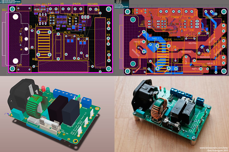
Schematic

Schematic for the UD2 Pre-charge board is available above for reference as part of the Creative Commons CC BY-NC 4.0.
===
For more enquires, please contact me at loneoceans [at] gmail [dot] com.
Back to loneoceans labs. (Updated May 2016)