
loneoceans labs | GXB20 v1 LED Driver PCB
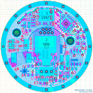
The GXB20 v1 LED Driver - click to enlarge for detail.
The GXB20 V1.0 is an experimental prototype, constant-current single-cell (e.g. 18650) Cree XHP50/70 Nichia 144 (6V 3A) Programmable Boost LED Driver. It was developed as an initial study to fill a gap in the hobby LED driver world for a high power programmable single-cell boost driver, and is currently undergoing continual development.
I’ve called this driver the GXB20. This is a no-frills true constant current driver which takes feedback from the drive current and regulates the output to match the desired current. I designed the driver to have a 20mm diameter to fit cheap 18650 LED flashlight hosts from Amazon/Ebay, with plans to develop a GXB17 when the design is more mature. The driver is fully programmable with an on-board ATtiny84A and includes other features such as temperature sensing and cut-off, LED brightness adjustment via constant-current limiting (no more PWM flickering!), battery voltage sensing, memory for various modes, and is designed to be able to supply the full 6 VDC 3A output with ~90+% efficiency via a boost circuit running off a single 3.7V lithium battery.
The driver has been verified to operate with good regulation up to 24W input, with an output of almost 3.3A and ~90% efficiency (even better efficiency approaching 95% at ~1.5A). Certainly changes can be made to increase output power at the expense of driver losses.
For most updated information on the status of this project, please see the related thread here: http://budgetlightforum.com/node/52517.
The GXB20 V1.0 is currently designed with the following features:
PCB: Version 1.0, as of Mar 2017
Firmware: v0.9 as of Mar 2017
These boards are currently being offered as-is blank PCBs:

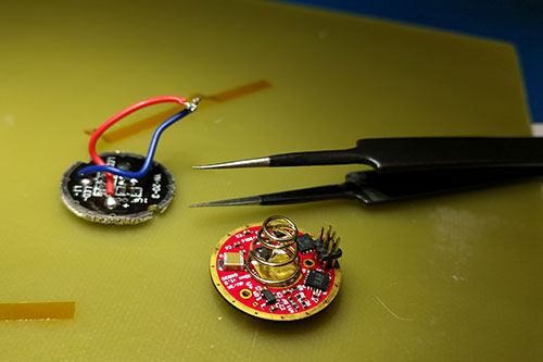
Note that the components on the board are small and you should be confident in being able to either solder it together with some sort of magnification equipment and small soldering irons, or using hot-air / reflow.
Shipping is from the USA to anywhere around the world (not included but usually relatively cheap) starting at $1 for regular shipping and handling within the US. All prices are in USD. Note that this is an experimental project and currently under development in both PCB and Firmware.
Contact loneoceans [at] g mail [dot] com for enquiries.

Schematic for the GXB20 v1 is provided above for reference, and distributed under the MIT GNU General Public License.
These are the components for the GXB20 v1. I purchase my components from Digikey or Mouser:
| Designator | Value | Package | Quantity | Part Number |
| B1, B2 | 47uF | 1210 Capacitor | 2 | GRM32ER61C476ME15L |
| B3 | 22uF | 1210 Capacitor | 1 | GRM32NR61A226KE19L |
| C1, C2, C3, C4, C5 | 1uF | 0402 Capacitor | 5 | GRT155R61E105KE01D |
| C10 | 33pF | 0402 Capacitor | 1 | GRM1555C1H330GA01D |
| C6 | 47nF | 0402 Capacitor | 1 | GCM155R71H473KE02D |
| C7, C8 | 100pF | 0402 Capacitor | 2 | GRM1555C1H101GA01D |
| C9 | 680pF | 0402 Capacitor | 1 | GRM1555C1H681GA01D |
| Ca, Cb, Cc, Cd, Cf | 0.1uF | 0402 Capacitor | 5 | GRM155R71H104ME14D |
| J1 | AVR ISP Small | PAD 2x3 50mil | 1 | 20021111-00006T4LF |
| L1 | 1uH | IHLP2525 | 1 | IHLP2525CZER1R0M01 |
| NT1 | 47kR ERT-J0EP473F | 0402 Resistor | 1 | ERT-J0EP473F |
| R1 | ERJ-B2CFR03V | 0612 Resistor | 1 | ERJ-B2CFR03V |
| R10, R11 | NO LOAD | 0402 Resistor | 2 | NO LOAD |
| R2 | 261kR | 0402 Resistor | 1 | ERJ-2RKF2613X |
| R3 | 115kR | 0402 Resistor | 1 | ERJ-2RKF1153X |
| R4 | 41.2kR | 0402 Resistor | 1 | ERJ-2RKF4122X |
| R5, R6, R7 | 47kR | 0402 Resistor | 3 | ERJ-2RKF4702X |
| R8 | 1M | 0402 Resistor | 1 | ERJ-2RKF1004X |
| R9 | 4.7kR | 0402 Resistor | 1 | ERJ-2RKF4701X |
| U1 | Regulator TPS61088 | PVQFN20 | 1 | TPS61088RHLR |
| U2 | ATtiny84A | QFN20M2 | 1 | ATTINY84A-MMHR |
| U3 | LDO Regulator | SC70-5 | 1 | TLV70028DCKR |
| U4 | Op Amp | DFN6 | 1 | TSV991AIQ1T |
| U5 | 200kR Digital Pot | TDFN8 3x3mm | 1 | MAX5424ETA+T |
Feel free to substitute any of these components for similar ones of your choice.
This is the current operating functionality for firmware version v0.9:

Download the hex files here for programming:
Files are distributed under the MIT GNU General Public License.
Programming of the GXB20 is done via the AVR ISP mk2.

You can purchase this programmer from your favourite electronics store such as
Digikey, Mouser or even eBay or Amazon.
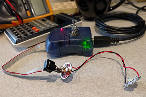
Due to the small size of the GXB20, there is no space for the standard 0.1" 2x3 header. Instead, pads are placed allowing 2x3 50mil headers to either be soldered on board, or simply pressed-in-place during programming. To connect to the 0.1" header, I soldered a female 0.05" socket to a 0.1" male header. See the photos above for how I programmed the GXB20. Power should be applied via a DC Power supply or battery for programming.
0.05" Male header part: GRPB032VWVN-RC
0.1" Female socket part: 20021321-00006C4LF
For maximum compatibility (and to be as hobbyist-friendly as possible), I wrote the firmware in the Arduino IDE v1.8.0. This is a free download here: https://www.arduino.cc/en/main/software
Since the microcontroller is an ATtiny84A, you will need ATtiny support in Arduino. After downloading Arduino, follow these instructions to install ATtiny support: http://highlowtech.org/?p=1695

When compiling, ensure that the board settings is set up as above.
Then ensure File>Preferences has "Verbose Output" checked. Next, click the 'tick' button to 'verify'. In the output below, the last 2 lines will display the file location for the .hex file.
Programming can then be done via Atmel Studio 7 using Tools>Device Programming, and the appropriate .hex file uploaded via the Memories Tab. Fuses can be left as factory default.
Ideas for improving so far (will be continually updated):
===
For more enquires, please contact me at loneoceans [at] gmail [dot] com.
(c) Gao Guangyan 2017 - All Rights Reserved.
Back to loneoceans labs. (Updated
Mar 2017)